Download
1 / 29
330 likes | 771 Views
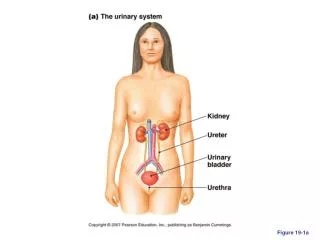
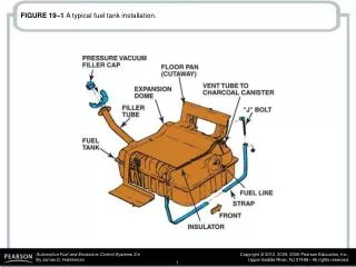
FIGURE 19–1 A typical fuel tank installation. FIGURE 19–2 A three-piece filler tube assembly.

E N D
FIGURE 19–3 A view of a typical filler tube with the fuel tank removed. Notice the ground strap used to help prevent the buildup of static electricity as the fuel flows into the plastic tank. The check ball looks exactly like a ping-pong ball.
FIGURE 19–4 Vehicles equipped with onboard refueling vapor recovery usually have a reduced-size fill tube.
FIGURE 19–5 The fuel pickup tube is part of the fuel sender and pump assembly.
FIGURE 19–6 On some vehicles equipped with an airflow sensor, a switch is used to energize the fuel pump. In the event of a collision, the switch opens and the fuel flow stops.
FIGURE 19–7 Ford uses an inertia switch to turn off the electric fuel pump in an accident.
FIGURE 19–8 Fuel lines are routed along the frame or body and secured with clips.
FIGURE 19–9 Some Ford metal line connections use springlocks and O-rings.
FIGURE 19–10 Ford spring-lock connectors require a special tool for disassembly.
FIGURE 19–13 The pumping action of an impeller or rotary vane pump.
FIGURE 19–14 An exploded view of a gerotor electric fuel pump.
FIGURE 19–15 A cutaway view of a typical two-stage turbine electric fuel pump.
FIGURE 19–16 A typical fuel-pump module assembly, which includes the pickup strainer and fuel pump, as well as the fuelpressure sensor and fuel level sensing unit.
FIGURE 19–17 A schematic showing that an inertia switch is connected in series between the fuel pump relay and the fuel pump.
FIGURE 19–18 A typical fuel pulsator used mostly with roller vane-type pumps to help even out the pulsation in pressure that can cause noise.
FIGURE 19–19 Inline fuel filters are usually attached to the fuel line with screw clamps or threaded connections. The fuel filter must be installed in the proper direction or a restricted fuel flow can result.
FIGURE 19–20 The final filter, also called a filter basket, is the last filter in the fuel system.
FIGURE 19–21 (a) A funnel helps in hearing if the electric fuel pump inside the gas tank is working. (b) If the pump is not running, check the wiring and current flow before going through the process of dropping the fuel tank to remove the pump.
FIGURE 19–22 The Schrader valve on this General Motors 3800 V-6 is located next to the fuel-pressure regulator.
FIGURE 19–23 The fuel system should hold pressure if the system is leak free.
FIGURE 19–24 If the vacuum hose is removed from the fuelpressure regulator when the engine is running, the fuel pressure should increase. If it does not increase, then the fuel pump is not capable of supplying adequate pressure or the fuel-pressure regulator is defective. If gasoline is visible in the vacuum hose, the regulator is leaking and should be replaced.
FIGURE 19–25 Fuel should be heard returning to the fuel tank at the fuel return line if the fuel pump and fuel-pressure regulator are functioning correctly.
FIGURE 19–26 A fuel-pressure reading does not confirm that there is enough fuel volume for the engine to operate correctly.
FIGURE 19–27 A fuel system tester connected in series in the fuel system so all of the fuel used flows through the meter which displays the rate-of-flow and the fuel pressure.
FIGURE 19–28 Removing the bed from a pickup truck makes gaining access to the fuel pump a lot easier.
FIGURE 19–29 Hookup for testing fuel-pump current draw on any vehicle equipped with a fuel-pump relay.