Download

1 / 27
270 likes | 400 Views
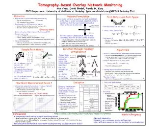
Tomography-based Overlay Network Monitoring. Yan Chen, David Bindel, and Randy H. Katz. UC Berkeley. Motivation. Applications of end-to-end distance monitoring Overlay routing/location Peer-to-peer systems VPN management/provisioning Service redirection/placement

E N D
Tomography-based Overlay Network Monitoring Yan Chen, David Bindel, and Randy H. Katz UC Berkeley
Motivation • Applications of end-to-end distance monitoring • Overlay routing/location • Peer-to-peer systems • VPN management/provisioning • Service redirection/placement • Cache-infrastructure configuration • Requirements for E2E monitoring system • Scalable & efficient: small amount of probing traffic • Accurate: capture congestion/failures • Incrementally deployable • Easy to use
Existing Work • Static estimation: • Global Network Positioning (GNP) • Dynamic monitoring • Loss rates: RON (n2measurement) • Latency: IDMaps, Dynamic Distance Maps, Isobar • Latency similarity under normal conditions doesn’t imply similar losses ! • Network tomography • Focusing on inferring the characteristics of physical links rather than E2E paths • Limited measurements -> under-constrained system, unidentifiable links
Overlay Network Operation Center End hosts topology measurements Problem Formulation Given n end hosts on an overlay network and O(n2) paths, how to select a minimal subset of paths to monitor so that the loss rates/latency of all other paths can be inferred. • Key idea: select a basis set of k paths that completely describe all O(n2) paths (k «O(n2)) • Select and monitor k linearly independent paths to compute the loss rates of basis set • Infer the loss rates of all other paths • Applicable for any additive metrics, like latency
A p1 1 3 Modeling of Path Space D C 2 B Path loss rate p, link loss rate l Put all r = O(n2) paths together Totally s links
link 2 A b2 (1,1,0) 1 3 b1 (1,-1,0) row space (measured) D null space (unmeasured) b3 C 2 link 1 B link 3 Sample Path Matrix • x1 - x2unknown => cannot compute x1, x2 • Set of vectors form null space • To separate identifiable vs. unidentifiable components: x = xG + xN • All E2E paths are in path space, i.e., GxN = 0
1’ 1 1 2 Rank(G)=1 1 1’ 2’ 2 1 2 3 Rank(G)=2 2’ 1’ 1 1 3’ 2 2 4 3 3 4’ Rank(G)=3 Intuition through Topology Virtualization • Virtual links: minimal path segments whose loss rates uniquely identified • Can fully describe all paths • xG : similar forms asvirtual links Virtualization Real links (solid) and all of the overlay paths (dotted) traversing them Virtual links
Algorithms • Select k = rank(G) linearly independent paths to monitor • Use rank revealing decomposition, e.g., QR with column pivoting • Leverage sparse matrix: time O(rk2) and memory O(k2) • E.g., 10 minutes for n = 350 (r = 61075) and k = 2958 • Compute the loss rates of other paths • Time O(k2) and memory O(k2)
How much measurement saved ? k « O(n2) ? For a power-law Internet topology • When the majority of end hosts are on the overlay, overlay network has O(n) IP links • When a small portion of end hosts are on overlay • If Internet a pure hierarchical structure (tree): k = O(n) • If Internet no hierarchy at all (worst case, clique): k = O(n2) • Internet has moderate hierarchical structure [TGJ+02] k = O(n) (with proof) For reasonably large n, (e.g., 100), k = O(nlogn)
BRITE 20K-node hierarchical topology Mercator 284K-node real router topology Linear Regression Tests of the Hypothesis • BRITE Router-level Topologies • Barbarasi-Albert, Waxman, Hierarchical models • Mercator Real Topology • Most have the best fit with O(n) except the hierarchical ones fit best with O(nlogn)
Practical Issues • Topology measurement errors tolerance • Care about path loss rates than any interior links • Poor router alias resolution => assign similar loss rates to the same links • Unidentifiable routers => add virtual links to bypass • Measurement load balancing on end hosts • Randomly order the paths for scan and selection of
Topology Changes • Basic building block: add/remove one path • Incremental changes: O(k2) time (O(n2k2) for re-scan) • Add path: check linear dependency with old basis set, • Delete path p : hard when The essential info described by p : • Add/remove end hosts , Routing changes • Topology relatively stable in order of a day => incremental detection
Evaluation • Simulation • Topology • BRITE: Barabasi-Albert, Waxman, hierarchical: 1K – 20K nodes • Real topology from Mercator: 284K nodes • Fraction of end hosts on the overlay: 1 - 10% • Loss rate distribution (90% links are good) • Good link: 0-1% loss rate; bad link: 5-10% loss rates • Good link: 0-1% loss rate; bad link: 1-100% loss rates • Loss model: • Bernouli: independent drop of packet • Gilbert: busty drop of packet • Path loss rate simulated via transmission of 10K pkts • Experiments on PlanetLab
Experiments on Planet Lab • 51 hosts, each from different organizations • 51 × 50 = 2,550 paths • Simultaneous loss rate measurement • 300 trials, 300 msec each • In each trial, send a 40-byte UDP pkt to every other host • Simultaneous topology measurement • Traceroute • Experiments: 6/24 – 6/27 • 100 experiments in peak hours
PlanetLab Experiment Results • Loss rate distribution • Metrics • Absolute error |p – p’ |: • Average 0.0027 for all paths, 0.0058 for lossy paths • Relative error [BDPT02] • Lossy path inference: coverage and false positive ratio • On average k = 872 out of 2550
Accuracy Results for One Experiment • 95% of absolute error < 0.0014 • 95% of relative error < 2.1
Accuracy Results for All Experiments • For each experiment, get its 95% absolute & relative errors • Most have absolute error < 0.0135 and relative error < 2.0
Lossy Path Inference Accuracy • 90 out of 100 runs have coverage over 85% and false positive less than 10% • Many caused by the 5% threshold boundary effects
Topology/Dynamics Issues • Out of 13 sets of pair-wise traceroute … • On average 248 out of 2550 paths have no or incomplete routing information • No router aliases resolved Conclusion: robust against topology measurement errors • Simulation on adding/removing end hosts and routing changes also give good results
Conclusions • A tomography-based overlay network monitoring system • Given n end hosts, characterize O(n2) paths with a basis set of O(nlogn) paths • Selectively monitor the basis set for their loss rates, then infer the loss rates of all other paths • Topology measurement error tolerance • Adaptive to topology changes • Both simulation and PlanetLab experiments show promising results • Built an adaptive overlay streaming media system on top of it
Work in Progress • Provide it as a continuous service on PlanetLab • Network diagnostics: Which links or path segments are down • Iterative methods for better speed and scalability
Sensitivity Test of Sending Frequency • Big jump for # of lossy paths when the sending rate is over 12.8 Mbps
Performance Improvement with Overlay • With single-node relay • Loss rate improvement • Among 10,980 lossy paths: • 5,705 paths (52.0%) have loss rate reduced by 0.05 or more • 3,084 paths (28.1%) change from lossy to non-lossy • Throughput improvement • Estimated with • 60,320 paths (24%) with non-zero loss rate, throughput computable • Among them, 32,939 (54.6%) paths have throughput improved, 13,734 (22.8%) paths have throughput doubled or more • Implications: use overlay path to bypass congestion or failures
Adaptive Overlay Streaming Media Stanford UC San Diego UC Berkeley X HP Labs • Implemented with Winamp client and SHOUTcast server • Congestion introduced with a Packet Shaper • Skip-free playback: server buffering and rewinding • Total adaptation time < 4 seconds
Conclusions • A tomography-based overlay network monitoring system • Given n end hosts, characterize O(n2) paths with a basis set of O(nlogn) paths • Selectively monitor O(nlogn) paths to compute the loss rates of the basis set, then infer the loss rates of all other paths • Both simulation and real Internet experiments promising • Built adaptive overlay streaming media system on top of monitoring services • Bypass congestion/failures for smooth playback within seconds