Download
1 / 20
200 likes | 399 Views
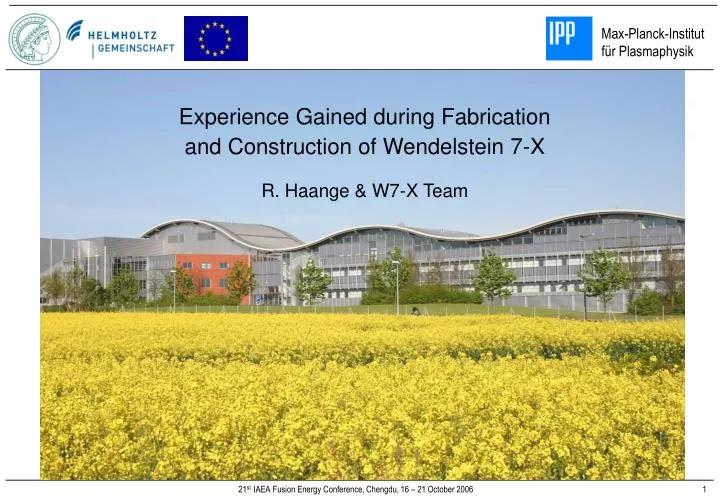
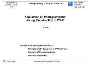
Experience Gained during Fabrication and Construction of Wendelstein 7-X R. Haange & W7-X Team. Overview. Introduction Status Design and Fabrication Experienced Gained during Design, Fabrication and Testing of Components Assembly of the W7-X Stellarator Conclusions and Recommendations.

E N D
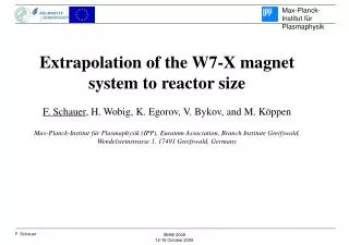
Experience Gained during Fabrication and Construction of Wendelstein 7-X R. Haange & W7-X Team
Overview • Introduction • Status Design and Fabrication • Experienced Gained during Design, Fabrication and Testing of Components • Assembly of the W7-X Stellarator • Conclusions and Recommendations
Introduction • W7-X is a fully optimised stellarator from a plasma physics point of view. This has resulted in a rather complex device that poses “interesting” challenges for its detailed engineering as well as for the assembly. • For diagnostics, cooling, plasma heating and other purposes adequate port space needs to be available. Due to the large number of coils, and their 3-D shape, space for ports is rather restricted. This has led to a large number (299) of mainly relatively small ports, some of which are of complex shape. • The remaining space in between coils for the mechanical structures is limited and has called for the development of novel designs.
Central support ring 20 Planar coils nominal current 16kA @ 4K @ 6T Plasma vessel 50 Non-planar coils nominal current 18.2kA @ 4K @ 6.7T Machine support Magnetic field on plasma axis 2.5 T (≤ 3T) Magnetic field at coils 6.7 T Magnetic energy ~ 620 MJ NbTi superconductor > 3.4 K Strand quantity 34 tonnes 50 non-planar coils 5 types 20 planar coils 2 types Cold mass ~ 400 tonnes W7-X is a fully optimized low-shear stellarator of the Helias type. Main Machine Layout
W7-X module assembly (1/5th) NbTi conductor with Al jacket Non-planar coil Planar coil W7-X Superconducting Coils
Thermal Insulation of the Plasma Vessel • Al-coated glass fibre panel with MLI • Cu-braids for connection to He-cooling pipe • MLI: 20 layers of crinkled, Al-coated Kapton foil Thermal insulation on a vacuum vessel sector
Parallel water-cooling, interface to feeder lines 10 MW/m2 10 MW/m2 1 MW/m2 Layout of Divertor • Target Baffle • Max. heat flux 10 MW/m2 1 MW/m2 • Total area 19 m2 5.6 m2 • Target modules 100 20 • Target elements 890 240
target elements 10 MW/m2CFC sealed on cooled CuCrZr being prepared for testing September 2006 • baffle elements 1 MW/m2graphite clamped on CuCrZr • cryopumps • control coils • more than 1.000.000 pieces • more than 100.000 pieces in the shop The Island Divertor
Rectification Requirements After manufacturing contracts had been placed: • Thorough FEM re-analyses showed that several structural members required strengthening. • Acceptance tests on non-planar coils showed, especially after warm-up following cold testing, insufficient voltage stand-off particularly in “Paschen-conditions” (low mbar range). This has required extensive repairs and re-testing, causing considerable delays to the start of machine assembly. • To minimise the delay, the use of two parallel assembly lines is being considered, which is, in principle, feasible for all assembly operations that take place outside the torus hall.
Reinforcement of parts of the central support ring Reinforcement of coil casing and support blocks Design Changes after Placing Manufacturing Contracts Narrow support elements: sliding pads in Al-Bronze Central support elements Welded lateral supports
Narrow Support Elements (NSE) Dust protection Spring Pad Pad frame Graph showing stick slip Exploded View on NSE
Cracks and cavities detected by Paschen tests Preparation of terminal region and typical Paschen discharge Paschen Tests
AAB16 Embedded Coil Crossing between Layers 9 & 10 Short Circuit in DLL5 AAB20 and AAB51 Windings Crossing between Layers 9 & 10 Short Circuit in DLL5 AAB51 Winding Crossing between Layers 3 & 4 Short Circuit in DLL2 Locations with high probability of turn-to-turn insulation fault Short Circuits in Type 1 & 5 Windings
Threading of non-planar coil type 3 across the PV sector. Non-planar coil type 3 fixed on top by adjustable poles. Achieved alignment accuracy is about 1 mm. Pre-assembly - Coil Threading
25 single bus-bars manufactured and mechanically mounted by Forschungszentrum Jülich Many different bearings which hold the bus-bars in bundles on the CSS Pre-assembly of Modules – Bus-bars
Torus hall - 1st ground-floor Mounting frame Module in the lower shell of the outer vessel Machine base Final Assembly 1st Stage – Module Completion
Conclusions and Recommendations Prototype testing of key components, like coils, heavily loaded structural components, etc. is important to demonstrate the principal feasibility of the design. However, for the series production it is often common to introduce, for various reasons, changes with respect to the prototypes, which can reduce the validity of the prototype tests by such an amount, that tests should be repeated. Moreover, in W7-X it has been found necessary to introduce changes after component fabrication had already started. For a complex first-of-a-kind machine, like the W7-X stellarator, the experience has shown that: • It is essential that at the start of such a project a thorough estimate is made of the manpower requirements for the various stages of the project and that manpower of adequate quality and quantity is recruited. • It is essential to have adequate expertise within the project team to ensure that the designs elaborated within the project are sound and that design and manufacturing proposals by manufacturers can be thoroughly reviewed by experienced and knowledgeable engineers and scientists. It is of utmost importance that the project is fully aware and understands the risks involved in the fabrication and test procedures that are commonly agreed. Although design reviews with external experts are a useful tool to find weaknesses in designs, in-house expertise is needed to control and supervise the work in-house and in factories.
Conclusions and Recommendations (iii) The engineering design of main components must have reached a mature status before manufacturing contracts should be placed. (iv) A thorough investigation of the preparedness of industries for the manufacturing and testing contracts is essential in judging the quality of work that can be expected as well as the expected punctuality of deliveries. (v) Instrumentation must be qualified for its intended use by testing under simulated conditions. (vi) Cold testing of coils, at least one or a few of each type, has been found to be mandatory in W7-X. Submitting coils to a few charge/discharge cycles at low temperature has been found useful in detecting manufacturing weaknesses. (vii) Tests in Paschen conditions after at least one cool-down/warm-up cycle are highly recommended. (viii) Divertor target elements should be tested in a HHF test facility prior to be assembled into components. (ix) Significant acceleration measures for machine assembly are possible by parallel work, but incur considerable additional investment costs. It is recommended that above experience be used for other fusion machines and that in particular cold testing of at least one coil of each type be carried out followed by tests in Paschen conditions.

![定理15.8:对 f(x) F[x],g(x) F[x], g(x) 0, 存在唯一的 q(x),r(x) F[x], degr(x)<degg(x) 或 r(x)=0, 使得:](https://cdn2.slideserve.com/4132616/slide1-dt.jpg)