Download
1 / 38
380 likes | 579 Views
ITC22 Nov. 19 ,2012 Toki(Japan). Improvement of heat conduction analysis of a small thermal probe. H. Matsuura a , S. Ohshima b , S. Hashimoto b , T. Mizuuchi b , K. Nagaoka c , H. Takeda d , Y. Nakashima d a Radiation Research Center, Osaka Prefecture University

E N D
ITC22 Nov.19,2012 Toki(Japan) Improvement of heat conduction analysis of a small thermal probe H. Matsuuraa, S. Ohshimab, S. Hashimotob, T. Mizuuchib, K. Nagaokac, H. Takedad, Y. Nakashimad aRadiation Research Center, Osaka Prefecture University bInstitute of Advanced Energy, Kyoto University cNational Institute for Fusion Science dPlasma Research Center, University of Tsukuba This work is partially performed with the support and under the auspices of the NIFS Collaborative Research Program. (NIFS12KUGM071/NIFS12KUHL047)
Background Diamag.(arb.) Nucl.Fusion 45 (2005) 1557-1570 Accurate estimate and control of divertor heat fluxare one of most urgent issue in fusion reactor design. Heat flux change due to H-mode, detachment, and so on is more interesting than steady state heat flux or total heat load per a whole discharge shot. Thermal probe (Calorimetric) method left the space for improvement to do it.
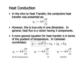
What is necessary for determination of heat flux q(t) with thermal probe? • Fitting procedure of measured TC data with response function model with physical causality • Response function of probe/calorimeter sensor with appropriate modeling • A small sensor with fast response (small thermal diffusion time) and good SN ratio
Fitting to TC data Heat flux evolution is approximated with the sum of step-like heat pulse.
Temperature response to step-like heat influx • Response time is given by thermal diffusion time. • Response amplitude is proportional to the squar of the heat flux multifid by sensor size. • If the sensor is cooled, response becomes difficult to detect.( In GAMMA 10, sensors are designed to be thermally isolated. )
Here we assume the infinite slab model with only plasma irradiation boundary.
Heat sink boundary Heat sink Kurihara, Kado (OS2006)
qsink=0 GAMMA 10 Calorimeter tip
Comparison of boundary condition Red: perfect sink boundary,Blue: perfect isolation boundary,Magenta: infinite boundary probe tip Plasma pulse
TC signal response improvement • use high thermal diffusivity materials such as Cu, Ag, and so on for probe tip • reduce the size of probe tip • set TC connection point as close as posible to plasma irradiation surface • Of course, need fast data logger
material Heat cond. [W/mK] T.Diffus. [mm^2/s] Time const. [s] * plasma Cu 398 117 1.0 H-J edge Kyoto Mo 138 54.3 1.8 MAP-Ⅱ Tokyo SUS 16 4.07 4.07 ICP Nagasaki Pylex Glass 1.089 0.686 146 glow OPU Heat conduction property of thermal probe tip * response time of TC below L=1[cm] from surface If the first TC is set 2mm, its time response is estimated to become smaller by factor of 0.04.
Comparison of the response for box heat pulse with two model 2MW/m2, 100ms 1MW/m2, 150ms heat sink boundary model thermal isolation boundary model Temperature at x=2,6,12[mm] is estimeted with two boundary model. Present (isolation boundary) model reproduces well the TC data. (OS2012)
GAMMA10 Calorimeter system The west end-mirror region, together with the location of the diagnostic equipment installed for this experiment.
New hybride probe(#8.5) Distance betweeen TC and surface is about 1.5mm, so response time of 10ms is expected. Cu tip is isolated thermally and electrically. Later may be cause the signal fluctuation. Other carbon pins are used for IS fluctuation measurement with other (#11.5 and #14.5) probes. B-line Flux B driving
Conclusion(What we did.) • We develop a new fitting procedure of measured TC data, and demonstrate with LHD probe data. • We expand response function model to be applicable to small sensors in HeliotronJ/GAMMA10. • We construct a new small sensor and test it in FY2012 experiment. Both in HeliotronJ/GAMMA10, TC noise problem is left.
What is left for future work? • Improvement of relibility on evaluated heat flux value or heat conduction model. Cross check of heat flux estimation • Comparison of Q-V characteristic of divertor plasma with those of low temperature discharge plasma • Design and construction of new sensors for Helioron J/GAMMA 10 to reduce or remove TC signal noise
Heat flux evalution of LHD plasma Anual. Report of NIFS(2011) presented at 21st ITC
HDP analysis(H-J) (Presented at ITC18/ITC19)
#7.5 Hybrid directional probe Pin3-5Cu diameter 4.5[mm] Type-K TC Cu 157.5 deg. section view
Long pulse discharge measurement Confinement transition due to biasing Delay of TC signal 0.7[s] delay 1-D const. Q model Thermal diffusion time of Cu
#8.5 Hybride probe (FY2011) #11.5 probe (old) New probe BN C Pin3 Pin2,4 double probe Pin1,5 floating potential Pin3 not work Pin3-->Temperature gradient type thermal probe
H-J用銅GTPのテスト ・約1センチのサイズで熱伝導率の良い銅を用いてGTPを試作し、4ピンのラングミュアプローブと組み合わせて複合プローブを構成した。 8.5ポート上側よりLCFSのX点近傍に挿入した。 熱電対信号には放電時のノイズが大きく、また放電後の温度上昇が見られない。 GTPが遮蔽されている?
H-J用銅GTP(#8.5port)の問題 ・プローブ駆動装置はプローブの軸方向に平行にLFCSに接近させる。そのため、磁力線は側面のBN部にあたり、GTPはイオンセンシティブプローブの様にイオンしか受け取ることが出来ない。 H-Jでは側面にセンサーが必要
Response of the old sensor The heat-flux density is evaluated from the difference between the temperature of the calorimeter tip measured just before the discharge and that measured immediately after the discharge. • Was Temperature evolution of TC data sufficiently traced? In FY 2010 experiment, time response of calorimeter sensor was slow, and data recorder also worked slowly. Calorimetric estimation One division is 16[min], nearly equal shot interval
TC signal noise During and just after discharge, there exist large noises in TC signal. They come from RF power,magnetic field induction, .... Noise at t=400-2000ms is well compensated with no plasma shot data.