Download
1 / 34
340 likes | 450 Views
Optical Tracking for VR. Bertus Labuschagne Christopher Parker Russell Joffe. Introduction. Project Motivation. Inexpensive Variable-light conditions Use low-resolution devices Did we mention inexpensive?. Project Breakdown. Christopher. Russell. Bertus. Christopher & Bertus.

E N D
Optical Tracking for VR Bertus Labuschagne Christopher Parker Russell Joffe
Project Motivation • Inexpensive • Variable-light conditions • Use low-resolution devices • Did we mention inexpensive?
Project Breakdown Christopher Russell Bertus Christopher & Bertus
Layer 1 Low-level image processing
Overview • Camera • Distortion example • Calibration • “Outside-in” model • Marker-based tracking • Thresholding • Sub-pixel accuracy • Search space reduction
Camera • Fundamental constraint of project: Low cost • Camera choice: Logitech webcam (< R150) • Camera may be prone to distortion need to calibrate
CameraDistortion Example VRVis Zentrum für Virtual Reality und Visualisierung Forschungs-GmbH http://www.vrvis.at/2d3d/technology/cameracalibration/cameracalibration.html
CameraCalibration • WHY? • Important for calculating accurate metric data • HOW? • Camera calibration toolkit.
“Outside-in” model • Markers are placed on the user • Cameras are fixed in position • Inside-out model: Cameras placed on users
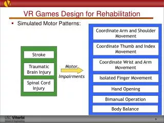
Marker-based tracking • Tasks: • Find position of markers in environment • Match corresponding markers from cameras • Extract marker centres
Marker-based trackingThresholding (1/4) • PURPOSE: Find regions in which markers are most likely to be • METHOD: Partition the image into background and foreground based on intensity threshold. • Problems?
Marker-based trackingThresholding (2/4) • Threshold too high • Localisation of only one marker
Marker-based trackingThresholding (3/4) • Threshold too low • Localisation of all markers • Extra background noise in foreground
Marker-based trackingThresholding (4/4) • Threshold just about right • Localisation of all three markers • Minor noise in image
Marker-based trackingSub-pixel accuracy • After thresholding, a large blob remains • We would like to find the centre of the light source • Naïve method: Take the brightest pixel in the area accurate to one pixel • Binary centroid: Take the average position of all points in the region, above the threshold • Weighted centroid: Treat positions of intensities above threshold as a mask and weight the points according to their original intensities
Marker-based trackingSearch space reduction Likely 3D position
Layer 2 Motion prediction & Model Generation
Overview • Tracking the current location and rotation of the user • Reducing latency in the system by using motion prediction • Ensuring the prediction coincides with the actual motion • Passing the information on to the environment
User Tracking • Common problems with user tracking • Latency • End-to-end delay from capturing data to updating the screen • Efficiency • Of the tracking algorithm • Accuracy • Accuracy of detecting changes in position and rotation
Motion Prediction I • Motivation • Reduce the effects of latency • Allows smooth transition between frames • Different inputs • For 2D input devices • For 3D input devices • Types of algorithms • Polynomial Predictor • Kalman based Predictor
Motion Prediction II • Existing vs new Algorithm • Existing algorithms • Might not be suited to our problem • May require modifications • May require new algorithm • Testing the efficiency and accuracy of implemented algorithms
Layer 3 Movement Processing
Layer 4 Virtual Environment
Overview • Movement data mapped to VE screen updates • Tracker vs. Standard Input (Keyb & Mouse) • Hypothesis: • “An optical tracking system works better for navigating through a virtual environment than conventional means”
Performance goals • High Accuracy • Low Latency Speed + Usability
2D / 3D Environments • OpenGL • 2D (non-walking) • Pacman type game • 3D (with walking) • Landscape / Game (undecided) • CAVEAT
Layer 4 User Testing
User testing techniques • Questionnaires • Hypothesis test • Continuous Assessment • Performance statistics • Interviews • Ethnographic Observation • Postural Response
Conclusions • Project consists of four sections • One section each • Layer 3, joins Layer 2 and Layer 4. • Final Outcome • Lastly a look at our deliverables
Deliverables • 20th June 2006 Obtain cameras • 30th June 2006 Get images from cameras • 20th September LED system built • 20th September Test centroid-finding algorithms • 20th September Test images for algorithms captured • 22nd September System design complete • 25th September VE design/User test design complete • 27th September 1st implementation of stand alone algorithms on images • 2nd October 2nd test of algorithms • 6th October All modules completed • 10th October 1st system integrated and running • 13th October Preliminary tests • 16th October Design for 2nd version