
Welcome!
Welcome!. Henny Penny World Headquarters. Class Schedule Training Materials (Books & CD’s) Safety & Exits Breaks Restrooms Smoking Areas Telephones Pagers & Cell Phones. Henny Penny LOV Fryer Installation Responsibilities List. Electrician

Welcome!
E N D
Presentation Transcript
Welcome! Henny Penny World Headquarters
Class Schedule • Training Materials (Books & CD’s) • Safety & Exits • Breaks • Restrooms • Smoking Areas • Telephones • Pagers & Cell Phones
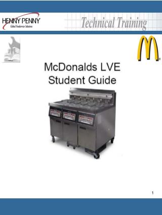
Henny Penny LOV Fryer Installation Responsibilities List Electrician 1) Connect exhaust fan electrical power connections and interlocks. 2) Test and check fan interlock circuit for proper operation with fryer(s). Plumber: 1) If gas fryers, assemble and connect gas manifold to flexible gas connection provided. 2) Assure proper gas pressure is present.
Henny Penny LOV Fryer Installation Responsibilities List Store Responsibilities: IMPORTANT: Please note that the LOV fryer is not a plug and play fryer. You must have your local FASC conduct start up and training prior to use. Please carefully coordinate the installation, check out and training. This must be accomplished in the proper order and immediately after one another. This is especially vital for replacement fryer installations. FASC start up and training must always occur on the same trip.
Henny Penny LOV Fryer Installation Responsibilities List Store Responsibilities: Continued • Coordinate the Fryer Check Out and Training with FASC prior to installation. • 2) Notify and schedule RTI if the location is a bulk oil location. Note: RTI will require an additional two hours of prep time per fryer prior to the FASC check out. • 3) Order Magnesol Filter pads to have on hand for training. Magnesol Universal Pad Kit #03190-054.
Henny Penny LOV Fryer Installation Responsibilities List Store Responsibilities: Continued 4) Install Fryer: The Store is responsible to have fryer installed by KES or other service agent. a) Uncrate fryer and install per installation procedures in manual b) Level the fryer c) Verify line power d) Dispose of old fryer if applicable e) Rinse and dry vats 5) Arrange to have key personnel available to attend two hour training session with FASC immediately after start-up.
Henny Penny LOV Fryer Installation Responsibilities List Basic Function of FASC Start UP: (Complete Checklist will be signed by manager) 1) Ensure fryer is properly fit restrained and level in accordance with specification 2) Perform SETUP on all computers. 3) GAS fryers, check incoming gas flow pressure with all vat burners on (Natural Gas: 4-6” W.C; LP Gas: 11-14” ) ELECTRIC fryers ensure applied voltage matches the rating plate.. 4) Test and confirm Auto Top Off system is working properly
Henny Penny LOV Fryer Installation Responsibilities List Basic Function of FASC Start UP: (Complete Checklist will be signed by manager) Continued 5) Verify that all filter parts (filter pan, filter screen, filter pad, hold-down ring, crumb tray, and O-rings) are present. Visually inspect the oil drain and return system to ensure all connections are tight. Perform filter cycle and verify operation. 6) Heat up each vat and confirm recovery time is less than (1:40 electric) (2:25 gas).
Henny Penny LOV Fryer Installation Responsibilities List Basic Function of FASC Training: (Complete checklist will be signed by manager) 1) Basic Overview of LOV Fryer concept & hands on demonstration of the following: 2) AIF Filter Operation 3) Maintenance Filter Operation 4) Filter Pan Cleaning 5) Control programming 6) Shortening Disposal 7) Deep Clean Process 8) Special Manager Information Mode
FR FRIES FR FRIES Left and Right Control The electronic control panel is a pushbutton control that includes a left and a right side control feature.
Full Vat Controller The Full Vat controller provides an assigned product timer for left and right side Baskets that share a common single Vat.
Split Vat Controller The Split Vat controller provides a product timer for individual left and right side Vats. A Split Vat can accommodate one basket.
Heat Light LED The “heat light” LED’s light when the control calls for heat.
Number 1 Pushbutton The number one pushbutton is used to start and stop a Product cook cycle. It is also used to answer “Yes”.
Number 2 Pushbutton The number two pushbutton is used to start and stop a Product cook cycle. It also is used to answer “No” to a prompt.
FLTR NOW Digital Display FR FRIES The electronic control visually displays programming, product cook cycle, filtering, and other information and messages.
Power Button The power button turns the associated controller on or off.
Product Pushbutton Press a product button to select a specific product.
Temp Pushbutton Touch the “Temperature” pushbutton to view the current oil temperature.
Filter Pushbuttons Pressing one “Filter” pushbutton will get you access to the filter menu, pressing both “Filter” pushbuttons will get into the Henny Penny Info Mode.
Info Pushbutton Touch the “Information” pushbutton to view the recovery time, access managers info mode, and toggle between languages.
Temp & Info Buttons Level 1 programming: Access Code 1-2-3-4 Product Programming AIF Clock Deep Clean Mode Fryer Setup Level 2 Programming: Access Code 1-2-3-4 Advanced Fryer Setup E-log Password Alert tone Filter After Filter Time
Temp & Info Buttons Level 3 programming: Access Code 1-1-2-2-1-1-2-2 Tech Resets Special Programming Clock Set Data Communications Heat Control Tech Mode Stats Mode
The controller has a left and right side control. The Heat light LED lights when calling for heat. Touch the “1” button to start/stop and answer “YES”. Touch the “2” button to start/stop and answer “NO”. The control display will show numerous messages. The power button turns the assigned control and heating element off. Use the Product button’s to select the desired product. The Filter pushbuttons are used for information mode and the filtering mode. The Information pushbutton will show the recovery time. Summary
Hinged Elements Cleaning Service LVE Heat System
2, 7KW Element (Full Vat) 1, 7KW Elements (Split Vat) LVE Heat System
Confirms heating elements are lowered Tilt switch LVE Heat System Element in up position Element in down position
High Limit thermostat LVE Heat System
Primary (Safety Contactor) Secondary (Heat Contactor) LVE Heat System
RTD’s (Temperature Probes) LVE Heat System
SAFETY CHAIN Block Diagram LVE Heat System Secondary (Heat) Contactor Primary (Safety) Contactor L1 L2 L3 L2 L3 L1 Heating Elements Electronic Controller AIF Drain Pan Switch Hi-Limit Tilt Switch RTD Probe
Hinged heating elements 7KW Controller monitors and regulates oil temperature. RTD’s measure oil temperature. Primary & Secondary Contactors energize heating element. High-Limit thermostat provides over-temp protection. Drain Switch confirms drain pan is in place. Tilt switch confirms heating elements are lowered. Summary LVE Heat System
1. Filter Ring 2. Crumb Basket 3. Filter Pan Cover 4. Filter Pad 5. Filter Screen 6. Drain Pan 1 2 3 4 5 6 Filter Pan Assembly LVE Automatic Filtering(AIF)
Filter Pan Assembly LVE Automatic Filtering(AIF)
Filter Pan Installation LVE Automatic Filtering(AIF)
PULL FR FRIES LVE Automatic Filtering(AIF) Auto Filter Cycle A cook cycle has ended, “PULL” is displayed touch “1” and remove product
FLTR NOW LVE Automatic Filtering(AIF) Auto Filter Cycle “Filter Now” ? will display
YES NO LVE Automatic Filtering(AIF) Auto Filter Cycle Select 1 for YES or 2 for NO
* SKIM * LVE Automatic Filtering(AIF) Auto Filter Cycle “SKIM” will prompt the operator to remove particles from the oil.
CONFIRM LVE Automatic Filtering(AIF) Auto Filter Cycle “CONFIRM” will display, select 1 to verify particles have been removed.
DRAINING LVE Automatic Filtering(AIF) Auto Filter Cycle “DRAINING” will display and the frypot will automatically empty.
WASHING LVE Automatic Filtering(AIF) Auto Filter Cycle “WASHING” indicates the frypot is automatically rinsing.
LVE Automatic Filtering(AIF) Auto Filter Cycle FILLING “FILLING” indicates the frypot is automatically refilling with oil.