Asynchronous Transfer Mode (ATM)
Asynchronous Transfer Mode (ATM). A Connection-oriented network providing Quality of Service guarantees developed in the mid-1980’s to combine packet switching with TDM had been hoped it would be the end-user to end-user network of choice to provide broadband services beyond ISDN

Asynchronous Transfer Mode (ATM)
E N D
Presentation Transcript
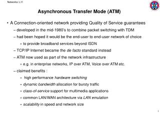
Networks: L11 Asynchronous Transfer Mode (ATM) • A Connection-oriented network providing Quality of Service guarantees • developed in the mid-1980’s to combine packet switching with TDM • had been hoped it would be the end-user to end-user network of choice • to provide broadband services beyond ISDN • TCP/IP Internet became the de facto standard instead • ATM now used as part of the network infrastructure • e.g. in enterprise networks, IP over ATM, Voice over ATM etc. • claimed benefits : • high performance hardware switching • dynamic bandwidth allocation for bursty traffic • class-of-service support for multimedia applications • common LAN/WAN architecture via LAN emulation • scalability in speed and network size
Networks: L11 Private ATM network Private UNI • An ATM network is a collection of endpoints, switches and interfaces : • UNI : user-network interface • connects end systems to switches • NNI : network-network interface • connects two switches • B-ICI : broadband intercarrier interface • connects two public switches from different service providers • provides Permanent Virtual Connections (PVCs) e.g. leased lines, and Switched Virtual Connections (SVCs) on demand X X Public UNI Private NNI Public ATM network A X X X Public UNI NNI X B-ICI Public ATM network B X Public UNI X X
Networks: L11 • ATM Technology • all information formatted into fixed-length cells of 48 bytes + 5 bytes header • ensures time-critical information not adversely affected by long packets • header organised for efficient hardware switching • carries payload type information, virtual-circuit identifiers, CRC etc. • information from separate flows converted into cells and then multiplexed • cells queued and transmitted according to some scheduling strategy • no time-slot reservation as in TDM • cells flow asynchronously Voice Data packets MUX Wasted bandwidth Images TDM 4 3 2 1 4 3 2 1 4 3 2 1 ATM ` 4 3 1 3 2 2 1
Networks: L11 • ATM is connection-oriented • a connection setup required prior to transfer of cells • identifies a path through the network that can provide the required service • a virtual channel connection (VCC) • the VCC has a chain of local identifiers each used at a switch (VCIs) • each input port to a switch uses its own private set of VCIs • used to index into its routing table to find the next hop output port • high speed switching relatively straightforward, 155Mbps streams typical • fixed sized cell with standard headers 1 1 voice 67 Switch … video 2 67 75 25 N video voice 32 5 25 67 32 1 data 3 39 3 32 39 video data 32 61 … 6 61 2 67 … N video 75 N
Networks: L11 • Aggregation into virtual paths: • virtual channel connections (VCC) sharing a common path through the network • VCCs a, b, c aggregated into VP3 after switch 1 • and to VP5 after the Digital Cross Connect to switch 2 • VCCs d, e aggregated into VP2 after switch 1 • and to VP1 after the DCC to switch 4 • VCCs b, c could have been aggregated after switch 2 to switch 3 • the DCC here switches aggregated virtual paths, not individual VCCs a VP3 VP5 a b ATM Sw 1 ATM Sw 2 b ATM DCC c ATM Sw 3 c d e VP2 VP1 d ATM Sw 4 e
Networks: L11 • Two levels of identifiers • Virtual Channel Identifier (VCI) and Virtual Path Identifier (VPI) • all switches along a virtual path switch on the basis of the VPI alone • VCIs only used at the end of a virtual path • the VCI/VPI structure supports scalability to very large networks • DCCs allow network path topology reconfiguration under software control • similar to SONET ring reconfigurability • network managers can allocate bandwidth to virtual paths • and to any degree of granularity Virtual Paths Physical Link Virtual Channels
Networks: L11 UNI cell NNI cell • ATM Cells: • GFC (Generic Flow Control) : local functions e.g. identifying multiple stations at end-points • not used in practice • no GFC in NNI header allows larger trunks between public ATM switches • VPI : 8 or 12 bits; VCI : 16 bits • PT (Payload Type) : payload contains user data/control data • CLP (Cell Loss Priority) : lower priority cells get discarded first when congested • HEC (Header Error Control) : CRC-8 (x8+x2+x+1) over first 4 bytes of header • detection and/or single bit correction VPI GFC VPI VPI VPI VCI VCI PT CLP PT CLP HEC HEC Payload (48 bytes) Payload (48 bytes)
Networks: L11 Management plane • Reference Model: • user plane deals with data transfer, flow control, error recovery etc. • control plane deals with signalling to set up, manage and release connections • management plane deals with network resources and coordination of other planes Plane management Control plane User plane Layer management Higher layers Higher layers Application Presentation ATM adaptation layer Session Transport ATM layer Network Data Link Physical Physical layer
Networks: L11 ATM layer Transmission convergence sublayer • Physical layer: • transmission convergence sublayer • ATM cell boundaries tracked • checking of header checksums • insertion and removal of idle cells • physical medium dependent layer • cells are converted into a bitstream • cells packaged into frames for the medium e.g. SONET, FDDI, STP etc. • ATM layer: • concerned with sequenced transfer of cells in connections across the network • accepts 48-byte blocks from the ATM Adaptation layer and adds 5-byte header Physical layer Physical medium dependent sublayer Physical medium User information User information AAL AAL ATM ATM ATM ATM PHY PHY PHY PHY … End system Network End system
Networks: L11 cells cells cells … • ATM Adaptation layer : • responsible for providing different applications with the appropriate support • several AAL types are defined – AAL1 to AAL5 • converts higher level SDUs into 48-byte blocks for ATM layer • provides support for the protocol layer directly above • e.g. to provide a reliable stream service, if needed (not if TCP was the layer above) • cell sequence numbering • segmentation and reassembly support AAL A/D Voice s1 , s2 … Digital voice samples Compression AAL Video A/D compressed frames picture frames AAL Data Bursty variable-length packets
Networks: L11 • Service Classes • Constant Bit Rate (CBR) • rate constant for the whole period of the connection • for traffic sensitive to delay • e.g. voice, video, TV, circuit switching emulation • Variable Bit Rate, non-real-time (VBR-NRT) • for bursty sources with no rigorous timing requirements • rate varies with time depending on rate at which application produces data • e.g. multimedia e-mail, transaction processing • Variable Bit Rate, real-time (VBR-RT) • similar to VBR-NRT for applications sensitive to cell-delay variation • e.g. voice with speech activity detection • Available Bit Rate (ABR) • allows sources to make use of any bandwidth that is still available • e.g. file transfer, e-mail • Unspecified Bit Rate (UBR) • for everything else, including TCP/IP – lowest tariff
Networks: L11 • Traffic Descriptors • parameters which the source must specify when negotiating a connection • traffic will be policed and enforced to conform with the parameters • Peak Cell Rate (PCR) • rate in cells/second that the source is never allowed to exceed • inverse of minimum inter-cell arrival time • Sustainable Cell Rate (SCR) • average cell rate in cells/second produced by the source over a long period • Maximum Burst Size (MBS) • number of consecutive cells that may be transmitted by the source at the PCR • used as the bucket size parameter for the enforcement algorithm • Minimum Cell Rate (MCR) • minimum cell rate in cells/second that the source is always allowed to send • Cell Delay Variation Tolerance (CDVT) • tolerable level of cell delay variation in a given connection
Networks: L11 • Negotiable Quality of Service parameters • Cell Loss Ratio (CLR) • ratio of number of lost cells to total transmitted cells • lost in the network due to congestion and/or buffer overflow • specified as an order of magnitude in the range 10-1 to 10-15 • extent to which CLR can be negotiated depends on buffer allocation strategies available in the network • Cell Transfer Delay (CTD) • delay experienced by a cell between network entry and exit • includes propagation delays, queuing delays at intermediate switches and processing times at queuing points • since cells each experience different delays, CTD specified by a probability density function • maximum CTD can be negotiated by which some fraction (1-) of the cells will be delivered • where is some appropriately small value
Networks: L11 probability density D0 Peak-to-Peak CDV Dmax • Cell Delay Variation (CDV) • the total delay encountered by cells in a connection • excluding fixed delay D0 • peak-to-peak delay can currently be negotiated • network switches have only limited control of the variance of CTD values • so range of negotiable CDV value is also limited
Networks: L11 • relevant parameters for service classes: • Connection Admission Control (CAC) • ensures that new virtual connections are assigned to links with sufficient bandwidth to meet the committed levels of Quality of Service • algorithms not standardised – left up to equipment suppliers • Policing • a Generic Cell Rate Algorithm (GCRA) defined • equivalent to the leaky bucket scheme
Networks: L11 Source Switch Transit Switch Destination Switch Source A Destination B • Connection establishment • setup, call proceeding, connect and connect acknowledgment messages: • ATM addressing • has its own system : telephony-oriented or private end-system addresses setup setup setup setup call proceeding call proceeding call proceeding call proceeding connect connect connect connect connect ack connect ack connect ack connect ack release release release release complete release release complete release complete release complete