Efficient Design Techniques for Large Digital Systems
Explore top-down design in large digital systems, involving controller and data processor separation. Learn to utilize flowcharts for clear algorithm depiction and systematic problem-solving.

Efficient Design Techniques for Large Digital Systems
E N D
Presentation Transcript
Outline • Large Digital Systems • Top-Down Approach • Controller and Data Processor • Flowcharts
Outline • Large Digital Systems • Top-Down Approach • Controller and Data Processor • Flowcharts
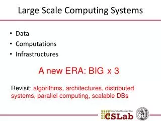
Large Digital Systems • In both combinational and sequential circuit design: • small circuits via gate-level design (truth tables, K maps, etc) • large circuits via block-level design (MSI components, etc.) • However, larger digital systems need more abstract and systematic design techniques. • One such systematic design method has the following characteristics: • top-down approach • separation of controller from controlled hardware • develop an overall architecture (at block levels) before proceeding into the details of hardware.
Outline • Large Digital Systems • Top-Down Approach • Controller and Data Processor • Flowcharts
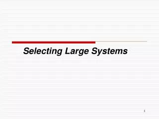
Top-Down Approach • Top-down approach is immensely important for large complex system (whether hardware, software, or manual systems). • Emphasis on macroscopic view, starting from original problem and gradually refine it towards solution. • Steps for a top-down design procedure: • Specify the problem clearly (at global/top level without unnecessary details). • Break the problem into smaller sub-problems. • Repeat the process until sub-problems are small enough to be solved directly (implementable).
Pass DLD Do Tutorials Pass Tests Pass Exam Ask questions Practice Revise Sleep well Top-Down Approach • Corresponds to goal-directed approach. • State goal, then find sub-goals to solve main goal. • Repeat until sub-goals are directly solvable.
Outline • Large Digital Systems • Top-Down Approach • Controller and Data Processor • Flowcharts
Controller & Data Processor • Digital systems are typically processors of information. • They store data through flip-flops, registers and memory, and process them using combinational circuits like adders, multipliers, etc. • These processing may pass through complicated sequences.
Status condition Commands Data Processor (Architecture) Control unit (Controller) External command Input data Output data Controller & Data Processor • A digital system consists of two components • A control algorithm (controller) and • An architecture (data processor)
Controller & Data Processor • Separation of the controller operations from the data processing operations • Control operations give commands that direct the data processing operations to accomplish the desired tasks. • Data processing operations manipulates the data according to requirements. • A mechanical analogy: Automobile. • Car (data processor): transports people from one location to another. • Driver (controller): gives instructions to car to achieve objective.
Outline • Large Digital Systems • Top-Down Approach • Controller and Data Processor • Flowcharts
Flowcharts • Flowcharts: a tool for precise description of algorithms/procedures. • Specify tasks to perform and their sequencing. • Main symbols: • Operation box: contains tasks/operations to perform. • Decision box: alternative actions based on decisions to be taken. • Arrows: indicate appropriate sequencing.
Sub-task or operation to perform Flowcharts • An operation box is rectangular in shape, and is used to specify one or more subtasks to be performed. It has at most one entry point and one exit point.
choice option A option B option C Flowcharts • A decision box is diamond-shaped. It has one entry point and multiple (but mutually exclusive) exit points.
Drink soup Main course Eat dessert Flowcharts • Sequential flow: simplest type of sequencing; tasks are done in sequential order. • An example: Eating a 3-course Western meal. • Boxes are connected by lines with arrows. Lines without arrows are sometimes used. In the absence of arrows, the default flow direction is top-to-bottom and left-to-right.
Flowcharts • Iteration: some tasks/operations may be repeatedly/iteratively done. • This is achieved through the loop-back in the flowchart. • Decision box is used to determine when to terminate the loop.
Drink soup Main course no enough? yes Eat dessert Flowcharts • An example: Eating a Western meal in oriental style.
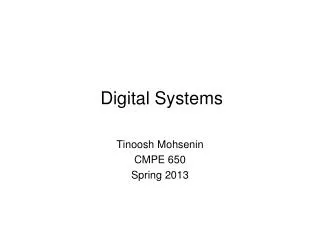
yes nice color & style? yes no affordable? no made in Europe? yes test out no poor fitting? acceptable insulting BF’s opinion? encouraging reject get BF to buy Flowcharts • Flowcharts can be used to implement complex decisions.