Download
1 / 60
600 likes | 777 Views
NIO GSMT Overview. VLOT/GSMT WORKSHOP Victoria, BC 17 JULY, 2001 S. Strom, L. Stepp. AURA NIO: Mission. In response to AASC call for a GSMT, AURA formed a New Initiatives Office (NIO) collaborative effort between NOAO and Gemini to explore design concepts for a GSMT NIO mission

E N D
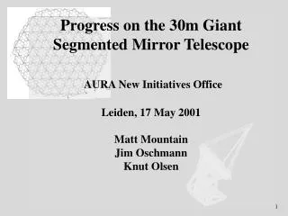
NIO GSMT Overview VLOT/GSMT WORKSHOP Victoria, BC 17 JULY, 2001 S. Strom, L. Stepp
AURA NIO: Mission • In response to AASC call for a GSMT, AURA formed a New Initiatives Office (NIO) • collaborative effort between NOAO and Gemini to explore design concepts for a GSMT • NIO mission “ to ensure broad astronomy community access to a 30m telescope contemporary in time with ALMA and NGST, by playing a key role in scientific and technical studies leading to the creation of a GSMT.”
Goals of the NIO • Foster community interaction on GSMT • Develop point design • Conduct studies of key technical issues and relationship to science drivers • Optimize community resources: • explore design options that yield cost savings, • emphasize studies that benefit multiple programs, • collaborate to ensure complementary efforts, • give preference to technologies that are extensible to even more ambitious projects.
R = 10,000 R = 1,000 R = 5 Comparative performance of a 30m GSMT with a 6.5m NGST Assuming a detected S/N of 10 for NGST on a point source, with 4x1000s integration GSMT advantage NGST advantage
Developing Science Cases • Two community workshops (1998-1999) • Broad participation; wide-ranging input • Tucson task group meetings (SEP 2000) • Large-scale structure; galaxy assembly • Stellar populations • Star and planet formation • NIO working groups (MAR 01 – SEP 01) • Develop quantitative cases; simulations • NIO-funded community task groups (CY 2002) • NIO-funded community workshop (CY 2002) • Define “Science Reference Mission”
KEY SCIENCE ENABLED BY GSMT Najita et al (2000,2001) Origin of structure in the universe: from the big bang to planetary systems
Tomography of the Universe • Goals: Map out large scale structure for z > 3 Link emerging distribution of gas; galaxies to CMB • Measurements: Spectra for 106 galaxies (R ~ 2000) Spectra of 105 QSOs (R ~15000) • Key requirements: 20’ FOV; >1000 fibers • Time to complete study with GSMT: 3 years • Issues • Refine understanding of sample size requirements • Spectrograph design
Hints of Structure at z=3 (small area) Existing Surveys + Sloan z~3 z~0.5 Mass Tomography of the Universe 100Mpc (5Ox5O), 27AB mag (L* z=9), dense sampling GSMT 1.5 yr Gemini 50 yr NGST 140 yr
Tomography of Galaxies and Pre-Galactic Fragments • Goals: Determine gas and stellar kinematics Quantify SFR and chemical composition • Measurements: Spectroscopy of H II complexes and underlying stars • Key requirements: Deployable IFUs feeding R ~ 10000 spectrograph Wide FOV to efficiently sample multiple systems • Time to complete study with GSMT: ~1 year • Issues • Modeling surface brightness distribution • Understanding optimal IFU ‘pixel’ size
Tomography of Individual Galaxies out to z ~3 • Determine the gas and stellar dynamics within • individual galaxies • Quantify variations in star formation rate • Tool: IFU spectra • [R ~ 5,000 – 10,000] GSMT 3 hour, 3s limit at R=5,000 0.1”x0.1” IFU pixel (sub-kpc scale structures) J H K 26.5 25.5 24.0
Origins of Planetary Systems • Goals: • Understand where and when planets form • Infer planetary architectures via observation of ‘gaps’ • Measurements: Spectra of 103 accreting PMS stars (R~105; l ~ 5m) • Key requirements: On axis, high Strehl AO; low emissivity • Time to complete study with GSMT: 2 years • Issues Understand efficacy of molecular ‘tracers’ Trades among emissivity; sites; telescope & AO design
Probing Planet Formation with High Resolution Infrared Spectroscopy • Planet formation studies in the infrared (5-30µm): • Probe forming planets in inner disk regions • Residual gas in cleared region low t emission • Rotation separates disk radii in velocity • High spectral resolution high spatial resolution S/N=100, R=100,000, >4m Gemini out to 0.2kpc sample ~ 10s GSMT 1.5kpc ~100s NGST X • 8-10m telescopes with high resolution (R~100,000) spectrographs can detect the formation of Jupiter-mass planets in disks around nearby stars (d~100pc).
Stellar Populations • Goals: Quantify IMF in different environments Quantify ages; [Fe/H]; for stars in nearby galaxies Develop understanding of galaxy assembly process • Measurements: Spectra of ~ 105 stars in rich, forming clusters (R ~ 1000) CMDs for selected areas in local group galaxies • Key requirements: MCAO delivering 2’ FOV; MCAO-fed NIR spectrograph • Time to complete study with GSMT: 3 years • Issues • MCAO performance in crowded fields
GSMT System Considerations Science Mission - DRM’s Adaptive Optics Active Optics (aO) Support & Fabrication Issues Full System Analysis Instruments GSMT Concept (Phase A) Site Characteristics Enclosure protection
NIO Approach Parallel efforts • Address challenges common to all ELTs • Wind-loading • Adaptive optics • Site • Explore point design • Start from a strawman • Understand key technical issues
Enemies Common to all ELTs • Wind….. • The Atmosphere……
Wind Loading • Primary challenge may be wind buffeting • More critical than for existing telescopes • Structural resonances closer to peak wind power • Wind may limit performance more than local seeing • Solutions include: • Site selection for low wind speed • Optimizing enclosure design • Dynamic compensation • Adaptive Optics • Active structural damping
AnimationWind pressure: C00030ootest_2, day_2, Azimuth angle=00, Zenith angle=30, wind_gate:open, open; wind speed=11 m/s
How to scale to 30 meters: RMS pressure differences D(d) = 0.076 d 0.43 30M Spatial scale
The Gemini South wind test results are available on the NIO Web site at: www.aura-nio.noao.edu
AO Technology Constraints:DMs and Computing power (50m telescope; on axis) r0(550 nm) = 10cm No. of Computer CCD pixel Actuator pitch S(550nm) S(1.65mm) actuators power rate/sensor (Gflops) (M pixel/s) 10cm 74% 97% 200,000 9 x 10⁵ 800 25cm 25% 86% 30,000 2 x 10⁴ 125 50cm 2% 61% 8,000 1,500 31SOR (achieved) 789 ~ 2 4 x 4.5 Early 21st Century technology will keep AO confined to l > 1.0 mm for telescopes with D ~ 30m – 50m
AO Technology Constraints:Guide stars and optical quality MCAO system analysis by Rigaut & Ellerbroek (2000): • 30 m telescope • 2 arcmin field • 9 Sodium laser constellation 10 watts each • 4 tip/tilt stars (1 x 17, 3 x 20 Rmag) • Telescope residual errors ~ 100 nm rms • Instrument residual errors ~ 70 nm rms System performance: l(mm) Delivered Strehl 1.25 0.2 ~ 0.4 1.65 0.4 ~ 0.6 2.20 0.6 ~ 0.8 PSF variations < 1% across FOV
Site Evaluation • ELT site evaluation more demanding • Evaluation criteria include • surface and high altitude winds • turbulence profiles • transmission • available clear nights (long-term averages) • cirrus cover (artificial guide star performance) • light pollution • accessibility • available local infrastructure • land ownership issues
Site Evaluation • NIO gathering uniform data for sites in: • Northern Chile • Mexico and Southwest US • Hawaii
Point Design: Philosophy • Select plausible design that addresses key science requirements • Identify key technical challenges • Focus analysis on key challenges • Evaluate strengths and weaknesses • guide initial cost-performance evaluation • inform concept design trades • Point design is only a strawman!
Point Design: Motivations • Provide a practical basis for wide-field, native seeing-limited instruments • science drivers strong • Explore a radio telescope approach • possible structural advantages • elevation bearing size comparable to primary • possible advantages in accommodating large instruments
Point Design: End-to End Approach • Science Requirements (including instruments) • Error Budget • Control systems • Enclosure concept • Interaction with site, telescope and budget • Telescope structure • Interaction with wind, optics and instruments • Optics • Interaction with telescope, aO/AO systems and instruments • AO/MCAO • Interaction with telescope, optics, and instruments • Instruments • Interaction with AO and Observing Model
30m Giant Segmented Mirror TelescopePoint Design Concept GEMINI 30m F/1 primary, 2m adaptive secondary
Key Point-Design Features • Paraboloidal primary • Advantage: Good image quality over 20 arcmin field with only 2 reflections • Seeing-limited observations in visible • Mid-IR • Disadvantage: Higher segment fabrication cost
Key Point-Design Features • F/1 primary mirror • Advantages: • Reduces size of enclosure • Reduces flexure of optical support structure • Reduces counterweights required • Disadvantages: • Increased sensitivity to misalignment • Increased asphericity of segments
Key Point-Design Features • Radio telescope structure • Advantages: • Cass focus can be located just behind M1 • Allows small secondary mirror – can be adaptive • Allows MCAO system ahead of Nasmyth focus • Disadvantage: • Requires counterweight • Sweeps out larger volume in enclosure
Controls Approach: Offloading Decentralized Controllers ~100 ~50 ~20 ~10 2 LGS MCAO spatial & temporal avg Zernike modes AO (M2) spatial & temporal avg aO (M1) spatial avg temporal avg spatial avg Secondary rigid body spatial & temporal avg Main Axes 0.001 0.01 0.1 1 10 100 Bandwidth [Hz]
GSMT Control Concept Deformable M2 : First stage MCAO, wide field seeing improvement and M1 shape control LGSs provide full sky coverage • M2: rather slow, large stroke DM to compensate ground layer and telescope figure, • or to use as single DM at >3 m. (~8000 actuators) • Dedicated, small field (1-2’) MCAO system (~4-6DMs). Active M1 (0.1 ~ 1Hz) 619 segments on 91 rafts 1-2’ field fed to the MCAO module 10-20’ field at 0.2-0.3” seeing Focal plane
Enabling Techniques Active and Adaptive Optics • Active Optics already integrated into Keck, VLT, Gemini, Subaru, Magellan, … • Adaptive Optics “added” to CFHT, Keck, Gemini, VLT, … Active and Adaptive Optics will have to be integrated into GSMT Telescope and Instrument concepts from the start
Enclosures Design options under study
Response to Wind Current concept will now go through “second iteration” of design in response to wind analysis
Adaptive M2 Intrinsic to Point Design • Options: low- to high-order • Compensate for wind-driven M1 distortions • Deliver high Strehl, mid-IR images with low emissivity • Deliver high-Strehl, near-IR images Goal: 8000 actuators 30cm spacing on M1
Key Point-Design Features • 2m diameter adaptive secondary mirror • Advantages: • Correction of low-order M1 modes • Enhanced native seeing • Good performance in mid-IR • First stage in high-order AO system • Disadvantages: • Increased difficulty (i.e., cost)
Sky Coverage vs Wavelength; Strehl for an Adaptive M2 (single laser guide star; Rigaut, 2001)
GSMT Implementation Concept- MCAO/AO foci and instruments Oschmann et al (2001) MCAO opticsmoves with telescope elevation axis 4m MCAO Imager at vertical Nasmyth Narrow field AO or narrow field seeing limited port
40 mm Pupil MCAO Near-IR Imager(1:1 Unfolded) ~2 arc minute field
Instruments • Telescope, AO and instruments must be developed as an integrated system • NIO team developing design concepts • Prime focus wide-field MOS • MCAO-fed near-IR MOS • MCAO-fed near-IR imager • AO-fed mid-IR HRS • Wide-field deployable IFU spectrograph • Build on extant concepts where possible • Define major design challenges • Identify needed technologies
Optical “seeing improvement”using low order AO correction Image profiles are Lorenzian 16 consecutive nights of adaptive optics the CFHT
Multi-Object Multi-Fiber Optical Spectrograph (MOMFOS) • 20 arc-minute field • 60-meter fiber cable • 800 0.7” fibers • 4 spectrographs, 200 fibers each • VPH gratings • Articulated collimator for different resolution regimes • Resolution Example ranges with single grating • R= 1,000 350nm – 650nm • R= 5,000 470nm – 530nm • R= 20,000 491nm – 508nm • Detects 13% - 23% of photons hitting the 30m primary
Prime Focus MOMFOS Barden et al (2001)