Download

1 / 82
830 likes | 864 Views
Discover the remarkable world of superconductors with near-zero resistance below a critical temperature and how they revolutionize technology, such as MRI units. Learn about direct current circuits, electromotive force, internal resistance, power distribution, and resistors in series. Explore the principles of energy conservation and circuit analysis in this informative guide. ###

E N D
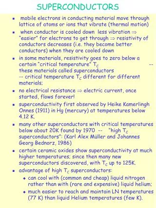
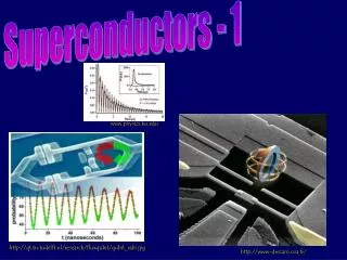
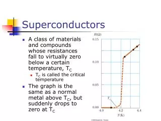
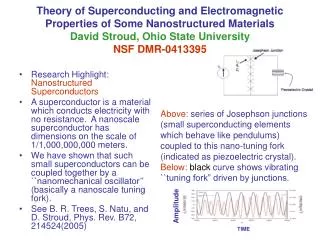
Superconductors • A class of materials and compounds whose resistances fall to virtually zero below a certain temperature, TC • TC is called the critical temperature • The graph is the same as a normal metal above TC, but suddenly drops to zero at TC
Superconductors, cont • The value of TC is sensitive to: • chemical composition • pressure • molecular structure • Once a current is set up in a superconductor, it persists without any applied voltage • Since R = 0
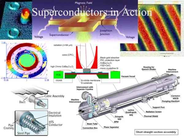
Superconductor Application • An important application of superconductors is a superconducting magnet • The magnitude of the magnetic field is about 10 times greater than a normal electromagnet • Used in MRI units
What would happen if all electric light filaments were replaced by superconducting filaments? • It would save over $100 billion a year in electric bills for U.S. • It would reduce the heat output of major cities • It would drop the cost of football tickets by 75% • It would allow people in the largest cities to see even the faintest stars in the sky.
Electrical Power, 2 • As the charge moves through the resistor (c to d), the system loses this electric potential energy during collisions of the electrons with the atoms of the resistor • This energy is transformed into internal energy in the resistor • Corresponds to increased vibrational motion of the atoms in the resistor
Electric Power, 3 • The resistor is normally in contact with the air, so its increased temperature will result in a transfer of energy by heat into the air • The resistor also emits thermal radiation • After some time interval, the resistor reaches a constant temperature • The input of energy from the battery is balanced by the output of energy by heat and radiation
Electric Power, 4 • The rate at which the system loses potential energy as the charge passes through the resistor is equal to the rate at which the system gains internal energy in the resistor • The power is the rate at which the energy is delivered to the resistor
Electric Power, final • The power is given by the equation: • Applying Ohm’s Law, alternative expressions can be found: • Units: I is in A, R is in Ω, V is in V, and is in W
Chapter 28 Direct Current Circuits
Direct Current • When the current in a circuit has a constant direction, the current is called direct current • Most of the circuits analyzed will be assumed to be in steady state, with constant magnitude and direction • Because the potential difference between the terminals of a battery is constant, the battery produces direct current • The battery is known as a source of emf
Electromotive Force • The electromotive force (emf), e, of a battery is the maximum possible voltage that the battery can provide between its terminals • The emf supplies energy, it does not apply a force • The battery will normally be the source of energy in the circuit • The positive terminal of the battery is at a higher potential than the negative terminal • We consider the wires to have no resistance
Internal Battery Resistance • If the internal resistance is zero, the terminal voltage equals the emf • In a real battery, there is internal resistance, r • The terminal voltage, DV = e – Ir • Use the active figure to vary the emf and resistances and see the effect on the graph
Active Figure 28.1 PLAY ACTIVE FIGURE
EMF, cont • The emf is equivalent to the open-circuit voltage • This is the terminal voltage when no current is in the circuit • This is the voltage labeled on the battery • The actual potential difference between the terminals of the battery depends on the current in the circuit
Load Resistance • The terminal voltage also equals the voltage across the external resistance • This external resistor is called the load resistance • In the previous circuit, the load resistance is just the external resistor • In general, the load resistance could be any electrical device • These resistances represent loads on the battery since it supplies the energy to operate the device containing the resistance
Power • The total power output of the battery is • This power is delivered to the external resistor (I2 R) and to the internal resistor (I2 r)
Resistors in Series • When two or more resistors are connected end-to-end, they are said to be in series • For a series combination of resistors, the currents are the same in all the resistors because the amount of charge that passes through one resistor must also pass through the other resistors in the same time interval • The potential difference will divide among the resistors such that the sum of the potential differences across the resistors is equal to the total potential difference across the combination
Resistors in Series, cont • Potentials add • ΔV = IR1 + IR2 = I (R1+R2) • Consequence of Conservation of Energy • The equivalent resistance has the same effect on the circuit as the original combination of resistors
Resistors in Series – Example • Use the active figure to vary the battery voltage and the resistor values • Observe the effect on the currents and voltages of the individual resistors PLAY ACTIVE FIGURE
Equivalent Resistance – Series • Req = R1 + R2 + R3 + … • The equivalent resistance of a series combination of resistors is the algebraic sum of the individual resistances and is always greater than any individual resistance • If one device in the series circuit creates an open circuit, all devices are inoperative
Equivalent Resistance – Series – An Example • Two resistors are replaced with their equivalent resistance
Some Circuit Notes • A local change in one part of a circuit may result in a global change throughout the circuit • For example, changing one resistor will affect the currents and voltages in all the other resistors and the terminal voltage of the battery • In a series circuit, there is one path for the current to take • In a parallel circuit, there are multiple paths for the current to take
Resistors in Parallel • The potential difference across each resistor is the same because each is connected directly across the battery terminals • A junction is a point where the current can split • The current, I, that enters a point must be equal to the total current leaving that point • I = I1 + I2 • The currents are generally not the same • Consequence of Conservation of Charge
Equivalent Resistance – Parallel, Examples • Equivalent resistance replaces the two original resistances
Equivalent Resistance – Parallel • Equivalent Resistance • The inverse of the equivalent resistance of two or more resistors connected in parallel is the algebraic sum of the inverses of the individual resistance • The equivalent is always less than the smallest resistor in the group
Resistors in Parallel – Example • Use the active figure to vary the battery voltage and the resistor values • Observe the effect on the currents and voltages of the individual resistors PLAY ACTIVE FIGURE
Resistors in Parallel, Final • In parallel, each device operates independently of the others so that if one is switched off, the others remain on • In parallel, all of the devices operate on the same voltage • The current takes all the paths • The lower resistance will have higher currents • Even very high resistances will have some currents • Household circuits are wired so that electrical devices are connected in parallel
What is the equivalent resistance of this circuit? • 50 Ω • 3.04 Ω • 17.9 Ω 0 of 30
What is the current through the center resistor? • 2 Amps • 0.84 Amps • 7 Amps • 0.32 Amps • 2.86 Amps 0 of 30
Combinations of Resistors • The 8.0-W and 4.0-W resistors are in series and can be replaced with their equivalent, 12.0 W • The 6.0-W and 3.0-W resistors are in parallel and can be replaced with their equivalent, 2.0 W • These equivalent resistances are in series and can be replaced with their equivalent resistance, 14.0 W
Gustav Kirchhoff • 1824 – 1887 • German physicist • Worked with Robert Bunsen • They • Invented the spectroscope and founded the science of spectroscopy • Discovered the elements cesium and rubidium • Invented astronomical spectroscopy
Kirchhoff’s Rules • There are ways in which resistors can be connected so that the circuits formed cannot be reduced to a single equivalent resistor • Two rules, called Kirchhoff’s rules, can be used instead
Kirchhoff’s Junction Rule • Junction Rule • The sum of the currents at any junction must equal zero • Currents directed into the junction are entered into the -equation as +I and those leaving as -I • A statement of Conservation of Charge • Mathematically,
More about the Junction Rule • I1 - I2 - I3 = 0 • Required by Conservation of Charge • Diagram (b) shows a mechanical analog
Kirchhoff’s Loop Rule • Loop Rule • The sum of the potential differences across all elements around any closed circuit loop must be zero • A statement of Conservation of Energy • Mathematically,
More about the Loop Rule • Traveling around the loop from a to b • In (a), the resistor is traversed in the direction of the current, the potential across the resistor is – IR • In (b), the resistor is traversed in the direction opposite of the current, the potential across the resistor is is + IR
Loop Rule, final • In (c), the source of emf is traversed in the direction of the emf (from – to +), and the change in the electric potential is +ε • In (d), the source of emf is traversed in the direction opposite of the emf (from + to -), and the change in the electric potential is -ε
Junction Equations from Kirchhoff’s Rules • Use the junction rule as often as needed, so long as each time you write an equation, you include in it a current that has not been used in a previous junction rule equation • In general, the number of times the junction rule can be used is one fewer than the number of junction points in the circuit
Loop Equations from Kirchhoff’s Rules • The loop rule can be used as often as needed so long as a new circuit element (resistor or battery) or a new current appears in each new equation • You need as many independent equations as you have unknowns
Kirchhoff’s Rules Equations, final • In order to solve a particular circuit problem, the number of independent equations you need to obtain from the two rules equals the number of unknown currents • Any capacitor acts as an open branch in a circuit • The current in the branch containing the capacitor is zero under steady-state conditions
Problem-Solving Strategy – Kirchhoff’s Rules • Conceptualize • Study the circuit diagram and identify all the elements • Identify the polarity of the battery • Imagine the directions of the currents in each battery • Categorize • Determine if the circuit can be reduced by combining series and parallel resistors • If so, proceed with those techniques • If not, apply Kirchhoff’s Rules
Problem-Solving Strategy, 2 • Analyze • Assign labels and symbols to all known and unknown quantities • Assign directions to the currents • The direction is arbitrary, but you must adhere to the assigned directions when applying Kirchhoff’s rules • Apply the junction rule to any junction in the circuit that provides new relationships among the various currents
Problem-Solving Strategy, 3 • Analyze, cont • Apply the loop rule to as many loops as are needed to solve for the unknowns • To apply the loop rule, you must choose a direction in which to travel around the loop • You must also correctly identify the potential difference as you cross various elements • Solve the equations simultaneously for the unknown quantities • Draw the circuit diagram and assign labels and symbols to all known and unknown quantities. Assign directions to the currents. • The direction is arbitrary, but you must adhere to the assigned directions when applying Kirchhoff’s rules • Apply the junction rule to any junction in the circuit that provides new relationships among the various currents
Problem-Solving Strategy, final • Finalize • Check your numerical answers for consistency • If any current value is negative, it means you guessed the direction of that current incorrectly • The magnitude will still be correct
RC Circuit, Example • Adjust the values of R and C • Observe the effect on the charging and discharging of the capacitor PLAY ACTIVE FIGURE