Download
1 / 80
800 likes | 826 Views
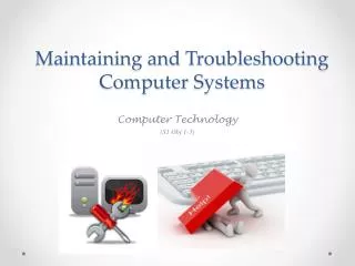
Ch. 5 Maintaining and Troubleshooting Routing Solutions. Materials. Book: Troubleshooting and Maintaining Cisco IP Networks (TSHOOT) Foundation Learning Guide: Foundation learning for the CCNP TSHOOT 642-832 By Amir Ranjbar Book ISBN-10: 1-58705-876-6 ISBN-13: 978-1-58705-876-9 eBook

E N D
Materials • Book: • Troubleshooting and Maintaining Cisco IP Networks (TSHOOT) Foundation Learning Guide: Foundation learning for the CCNP TSHOOT 642-832 • By Amir Ranjbar • Book • ISBN-10: 1-58705-876-6 • ISBN-13: 978-1-58705-876-9 • eBook • ISBN-10: 1-58714-170-1 • ISBN-13: 978-1-58714-170-6
Troubleshooting Routing • Network Layer Connectivity • EIGRP • OSPF • Route Redistribution • Note: You always have the option of reviewing my CCNP ROUTE PowerPoints or attending the lectures for a review. • At the time of this presentation we will be discussing Manipulating Routing Updates with route maps and distribution lists in my CIS 185 ROUTE class on Tuesday.
Network Connectivity • Just like we did when we looked at Layer 2 connectivity • To troubleshoot Layer 3 connectivity, you need to have a good understanding of the processes that are involved in routing a packet from a host through multiple routers to the final destination. • Lack of network layer connectivity indicates that the problem is at or below network layer.
Which decisions does Host A make to successfully send a packet destined for Host B to the first hop Router C? • What information does it need? • Addressing; ARP Cache • Which actions does it perform? • DHCP Request; Host or GW Address; DNS Query; ARP Request; Layer 2 encapsulation • Which decisions does Router C make to successfully send the packet from Host A destined for Host B to the next hop Router D? • TTL – ICMP Time Exceeded; ; CEF or layer 3; Longest prefix match; Layer 2 Next-hop address; layer 2 encapsulation; Fragmentation • Which decisions does Router D make to successfully send the packet from Host A destined for Host B to the next hop Router E? (Same questions) • Which decisions does Router E make to successfully send the packet from Host A destined for Host B to its final destination, Host B? (Same questions) • Are there any differences in the processes and information required in order to successfully transmit return packets from Host B back to Host A?
Alex Zinin’s Routing Table Principles I know about my remote networks but it is not my responsibility if R2 and R3 know about their remote networks. • Principle 1: Every router makes its decision alone, based on the information it has in its own routing table. • R1 makes forwarding decisions based solely on the information in the routing table. • R1 does not consult the routing tables in any other routers. • Making each router aware of remote networks is the responsibility of the network administrator.
Alex Zinin’s Routing Table Principles Just because I know how to get to R3’s LAN, 192.168.2.0/24 and I send that packet to R2, doesn’t mean R2 knows how to get there. ??? • Principle 2: The fact that one router has certain information in its routing table does not mean that other routers have the same information.
Alex Zinin’s Routing Table Principles And if the packet for R3’s LAN reaches 192.168.2.0/24, I don’t know if R3 has a route back to 172.16.3.0/24 for any return traffic. ??? • Principle 3: Routing information about a path from one network to another does not provide routing information about the reverse, or return, path.
To forward packets, a router combines information from various control plane data structures. • The most important of these data structures is the routing table. • Other structures include: • LSDB or topology table • Neighbor table • ARP or Frame Relay Map table • Unlike switches, which flood unknown frames, routers drop any packet for which they cannot find a matching entry in the routing table. • Searches for longest possible prefix match of the destination IP address. • Associated with this entry is an egress interface - most cases, a next-hop IP address.
The mapping between the next hop-IP address and the Layer 2 address or identifier is stored in a data structure that is specific for that Layer 2 protocol. • Ethernet: ARP cache • Frame Relay: Frame Relay map table (except for point-to-point) • A routing table lookup may need to be followed up by a lookup in a Layer 3 to Layer 2 mapping table to construct a frame, encapsulate the packet, and transmit it.
At a high level, each routing protocol consists of the following elements and processes: (RIP is a notable exception to some of these.) • Reception of routing information from neighbors: • Neighbor relationships • Routing protocol data structures: • Neighbor table, topology table • Route injection or redistribution: • Directly connected, dynamic routes, static routes • Route selection and installation: • Best path, equal cost load balancing, unequal cost load balancing • Transmission of routing information to neighbors: • Summarization, Broadcast, Multicast, LSAs, Route updates, ACKs
To diagnose and resolve problems related to EIGRP you must be able to: • Apply your knowledge of EIGRP data structures • Neighbor table, Topology Table • Apply your knowledge of EIGRP processes • DUAL, adjacency process, summarization, load balancing • Use Cisco IOS commands to gather information from the EIGRP data structures and track the flow of EIGRP routing information • Note: As we will see these procedures can be applied to other routing protocols as well.
R3# show ip eigrp interfaces IP-EIGRP interfaces for process 1 Xmit Queue Mean Pacing Time Multicast Pending Interface Peers Un/Reliable SRTT Un/Reliable Flow Timer Routes Se0/1 1 0/0 60 0/15 299 0 Se0/0 1 0/0 607 0/15 3031 0 Se0/2 1 0/0 29 0/15 143 0 Se0/3 1 0/0 24 0/17 50 0 R3# EIGRP stores its operational data, configured parameters, and statistics in three main data structures: • Interface table: • Lists all interfaces that have been enabled for the processing of EIGRP packets • Passive interfaces are not listed in this table.
R3# show ip eigrp neighbors IP-EIGRP neighbors for process 1 H Address Interface Hold Uptime SRTT RTO Q Seq Type (sec) (ms) Cnt Num 3 10.0.0.18 Se0/3 13 00:17:37 24 200 0 5 2 10.0.0.14 Se0/2 14 00:17:50 29 200 0 4 1 10.0.0.5 Se0/0 14 00:23:35 607 3642 0 13 0 10.0.0.9 Se0/1 12 00:24:01 60 360 0 21 R3# • Neighbor table: • Keeps track of all active EIGRP neighbors. • Neighbors are added to this table on the reception of hello packets • Neighbors are removed when: • Hold-time expires • Interface goes down or is removed from the interface table
R3# show ip eigrp topology <output omitted> P 10.0.0.0/30, 2 successors, FD is 2681856 via 10.0.0.9 (2681856/2169856), Serial0/1 via 10.0.0.5 (2681856/2169856), Serial0/0 <output omitted> P 172.16.0.0/16, 1 successors, FD is 2172416 via 10.0.0.14 (2172416/28160), Serial0/2 via 10.0.0.18 (2312192/28160), Serial0/3 FS if Reported Distance is less than Feasible distance Feasible distance successor feasible successor • Topology table: • Holds all the routes that were received from neighboring routers, locally injected, or redistributed into EIGRP. • EIGRP will select the best path from among the available possible paths • EIGRP’s best path selection is based on the Diffusing Update Algorithm (DUAL). Feasible distance: if this router was the successor.
Initial Route Discovery A B Updated Updated EIGRP Neighbor Table EIGRP Neighbor Table Hello, I am Router A. Is anyone there? Hello, I am Router B. Here is all my routing information. I’m using split horizon. Updated Updated EIGRP Topology Table EIGRP Topology Table Thanks for the information! That is very nice of you. Successor Successor Here is all my routing information. I’m also using split horizon. Updated Updated IP Routing Table IP Routing Table Thanks for the information! We’ve reached convergence.
After the initial updates have been exchanged, routing updates will only be exchanged as a result of changes on the networks. • Changes can be caused by changes in connectivity, such as: • Loss of a link or neighbor • Configuration events
R2# debug ip routing IP routing debugging is on R2# conf t R2(config)# int fa0/0 R2(config-if)# ip address 172.16.1.1 255.255.255.0 R2(config-if)# no shutdown %LINK-3-UPDOWN: Interface FastEthernet0/0, changed state to up %LINEPROTO-5-UPDOWN: Line protocol on Interface FastEthernet0/0, changed state to up RT: add 172.16.1.0/24 via 0.0.0.0, connected metric [0/0] RT: interface FastEthernet0/0 added to routing table • debug ip routing: • Not specific to EIGRP • Displays any changes that are made to the routing table, such as installation or removal of routes.
debug eigrp packets: • Displays the transmission and reception of EIGRP packets. • Note: Cisco Press Implementing Cisco IP Routing (ROUTE) by Diane Teare provides detailed explanation of the output.
debug ip eigrp: • Displays EIGRP routing events, such as updates, queries, and replies sent to or received from neighbors. • Focuses on the routing information contained in the packets and the actions that EIGRP takes as a result of the information received. • Note: Cisco Press Implementing Cisco IP Routing (ROUTE) by Diane Teare provides detailed explanation of the output.
Troubleshooting Example: Routing Problem in an EIGRP Network
ping from BRO1 to CRO1 succeeds, you can conclude that the WAN link is operational at Layers 3 and below
Two likely reasons why the traffic is routed through router BRO2 instead of directly across the WAN to router CRO1: • BRO1 has not learned about the direct route to router CRO1. • BRO1 selects the route through router BRO2 as the best route. • Let’s look at the EIGRP topology table
The topology table lists all routes that were received, so you can see if the direct route to CRO1 is missing. • Note: This command displays all entries in the topology table for this destination, not just feasible successors – similar to “all-links” option. • No direct route! • Need to determine whether the route was not learned because: • A neighbor relationship with CRO1 was never established • The relationship was established but the specific route was not exchanged. • Good next step is to display the neighbor table
CRO1 is not listed as a neighbor on router BRO1. • Could be one or the other routers is not: • Sending Hello packets • Ignoring Hello packets • Let’s look at the EIGRP interfaces to make sure the serial interface is configured for EIGRP.
Does not list the serial interface of router BRO1. • So, even if hello packets are received on the serial interface, router BRO1 does not process them. • Two conditions need to be met for an interface to be added to the EIGRP interface table: • The interface has to be up and its IP address must match one of the configured network statements. • The interface should not be configured as a passive interface. • Let’s look at the running-config…
Problem with one of the network statements. • The statement network 10.1.194.1 0.0.0.0 matches IP address 10.1.194.1 the IP address of router CRO1 • Does not match the serial interface of BRO1 • Replaced it with the statement network 10.1.194.2 0.0.0.0 or some other network statement
The interface table now lists subinterface Serial 0/0/0.111 in addition to subinterface FastEthernet 0/1.30. • This means that EIGRP packets are now processed on interface Serial 0/0/0.111. • IP address of router CRO1 (10.1.194.2) is now listed in the neighbor table on the WAN interface.
Successor • The EIGRP topology table now lists two entries for network 10.1.220.1/32. • Note: BR02 is listed but is not a Feasible Successor (RD is not less than FD)
show ip route command with network 10.1.220.1 confirms that the path through router CRO1 has been installed in the routing table • traceroute command confirms that this path is now used to forward packets to the loopback of CRO1.
To diagnose and resolve problems related to OSPF you must be able to: • Apply your knowledge of OSPF data structures • Apply your knowledge of OSPF processes within an area • Apply your knowledge of OSPF processes between areas • Use Cisco IOS commands to gather information from the OSPF data structures and track the flow of OSPF routing information
R1# show ip ospf interface serial 0/0/0 Serial0/0/0 is up, line protocol is up Internet Address 192.168.10.1/30, Area 0 Process ID 1, Router ID 10.1.1.1, Network Type POINT_TO_POINT, Cost: 64 Transmit Delay is 1 sec, State POINT_TO_POINT, Timer intervals configured, Hello 10, Dead 40, Wait 40, Retransmit 5 <output omitted> • OSPF stores its operational data, configured parameters, and statistics in four main data structures: • Interface table: • Lists all interfaces that have been enabled for OSPF. • When an interface is configured as a passive interface, it is still listed in the OSPF interface table, but no neighbor relationships are established on this interface.
R1# show ip ospf neighbor Neighbor ID Pri State Dead Time Address Interface 10.3.3.3 1 FULL/ - 00:00:30 192.168.10.6 Serial0/0/1 10.2.2.2 1 FULL/ - 00:00:33 192.168.10.2 Serial0/0/0 • Neighbor table: • Keeps track of all active OSPF neighbors. • OSPF goes through a number of states while establishing a neighbor relationship (also known as adjacency) • Lists the current state for each individual neighbor
Link-state database: • This is the main data structure that OSPF uses to store all its network topology information. • Contains a wealth of network topology information • One of the most important data structures to gather information from when troubleshooting OSPF problems.
R33# show ip route 33.0.0.0/32 is subnetted, 1 subnets C 33.33.33.33 is directly connected, Loopback0 172.16.0.0/24 is subnetted, 2 subnets C 172.16.1.0 is directly connected, FastEthernet0/0 O 172.16.2.0 [110/2] via 172.16.1.1, 00:02:13, FastEthernet0/0 172.30.0.0/24 is subnetted, 2 subnets C 172.30.1.0 is directly connected, FastEthernet0/1 O 172.30.2.0 [110/2] via 172.16.1.3, 00:02:23, FastEthernet0/0 O*IA 0.0.0.0/0 [110/2] via 172.16.1.1, 00:02:13, FastEthernet0/0 • Routing information base: • After executing the SPF algorithm, the results of this calculation are stored in the RIB (Routing Information Base). • Routes might be added to or deleted from the RIB without the need for a SPF recalculation. • From the RIB, OSPF offers its routes to the IP routing table. • Note: The collection of best paths is known as the OSPF RIB. • There is not a separate physical data structure called the OSPF RIB. • Many writings refer to the IP routing table as the RIB to allow it to be distinguished from the FIB that CEF creates.
R1# show ip ospf neighbor Neighbor ID Pri State Dead Time Address Interface 10.3.3.3 0 FULL/ - 00:00:35 192.168.10.6 Serial0/0/1 10.2.2.2 0 FULL/ - 00:00:36 192.168.10.2 Serial0/0/0 • Two routers will become neighbors only if the following parameters match in the Hello packets: • Hello and dead timers: • Use the same Hello and dead time. • Broadcast and point-to-point type networks are 10-second Hello and 40-second dead time. • OSPF area number: • Both consider that link to be in the same area. • IP subnet and subnet mask: • If they are on the same subnet. • The exception to this rule is on a point-to-point link, where the subnet mask is not verified.
CR01# show ip route 10.1.152.0 • Examine the routing table on router CRO1, you only find a single entry, the path through router CSW1. • Should be two equal cost paths
This result is unexpected because there are two equal cost paths are available to CRO1: • via CSW1 • via CSW2 • Ping CSW2 • Because this ping succeeds, conclude that the Fast Ethernet link between router CRO1 and router CSW2 is operational at Layers 3 and below. • Need to find out why the second, equal cost path through router CSW2 is not installed in the routing table • There are two main reasons why this could be happening. • CSW2 is not advertising subnet 10.1.152.0/24 to area 0 • Cost to reach subnet 10.1.152.0/24 through router CSW2 from router CRO1 is considered to be worse than the cost through router CSW1.
Therefore, the preference for the path to 10.1.152.0/24 via CSW1 must be based on the topology within area 0. • Given that router CRO1 has a direct connection in area 0 to both router CSW1 and CSW2, there are only two plausible explanations for the fact that router CRO1 is not using the path via router CSW2. • Either the direct path to router CSW2 is not used because routers CSW2 and CRO1 have not become neighbors • The path is not used because the cost for interface FastEthernet 0/1 is higher than the cost for interface FastEthernet 0/0
Note: Unlike the show ip eigrp interfaces command, the show ip ospf interface command will display interfaces that are enabled for OSPF, but configured as passive interfaces. • To verify if router CRO1 has established, a proper neighbor relationship with router CSW1, the show ip ospf neighbor • There could be several reasons why router CSW2 is not listed as a neighbor of CRO1: • CSW2 is not sending Hellos • Hellos are received, but ignored due to mismatched Hello parameters. • Hellos are sent, but not received, because interface FastEthernet 0/1 has not been activated for OSPF and therefore does not listen to the OSPF multicast group 224.0.0.5
The is a problem with one of the network statements. • The statement network 10.1.192.9 0.0.0.0 area 0 matches IP address 10.1.192.9, which is not one of router CRO1’s IP addresses, but an IP address of router CSW2. • network statement needs to be replaced with the statement network 10.1.192.10 0.0.0.0 area 0 or some other network statement
Troubleshooting the book • Through no fault of the author the diagram in the book is incorrect. • Why is this diagram incorrect given this output? • CR01 cannot receive LSA 3’s from CSW2 unless: • Establishes a neighbor adjacency with CSW2 • CSW2 forwards the LSA3 to CSW1 within area 0 (CR01’s area)
Ideally, no more than one interior (intra-AS) routing protocol is used within an organization. • Reasons for running multiple routing protocols: • Company mergers and different IGPs are used • Company has different divisions with the network under separate control for business or political reasons • Company has connections between business partners • To allow multivendor interoperability (OSPF on non-Cisco, EIGRP on Cisco, for instance) • Improper route redistribution can lead to: • Suboptimal routing • Routing feedback (routing loops)