Download
1 / 113
1.14k likes | 1.53k Views
Explore how torque transforms to kinetic energy in mixers & compactors. Study kinetic energy equations & work principles applied to rigid bodies in translational & rotational motion. Learn about forces that do no work and the principle of work and energy.

E N D
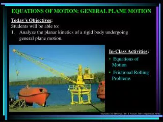
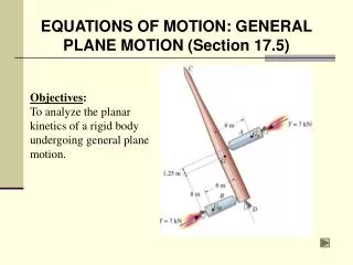
CHAPTER 18 PLANAR KINETICS OF A RIGID BODY: WORK AND ENERGY (Sections 18.1-18.4) Objectives: a) Define the various ways a force and couple do work. b) Apply the principle of work and energy to a rigid body.
APPLICATIONS The work of the torque developed by the driving gears on the two motors on the mixer is transformed into the rotational kinetic energy of the mixing drum. The work done by the compactor's engine is transformed into the translational kinetic energy of the frame and the translational and rotational kinetic energy of its roller and wheels
KINETIC ENERGY The kinetic energy of a rigid body in general plane motion is given by T = 1/2 m (vG)2 + 1/2 IG ω2 • Several simplifications can occur. • Pure Translation: the rotational kinetic energy is zero (ω = 0): • T = 0.5 m (vG)2
KINETIC ENERGY (continued) 2. Rotation: When a rigid body is rotating about a fixed axis passing through point O, the body has both translational and rotational kinetic energy: T = 0.5m(vG)2 + 0.5IGw2 Since vG = rGw, T = 0.5(IG + m(rG)2)w2 = 0.5IOw2 If the rotation occurs about the mass center (pure rotation), G, then vG=0 T = 0.5 IG w2
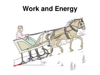
The work done by a force is UF = F•dr = (F cos θ) ds Constant force : UFc = (Fc cos θ)s s WORK OF A FORCE Work of a weight: Uw = -WΔy. Work of a spring force: Us = -0.5k[(s2)2 – (s1)2]
FORCES THAT DO NO WORK 1. Reactions at fixed supports because the displacement at their point of application is zero. 2. Normal and frictional forces acting on bodies as they roll without slipping over a rough surface since there is no instantaneous displacement of the point in contact with ground. 3. Internal forces because they always act in equal and opposite pairs.
If the body rotates through an angular displacement dq, the work of the couple moment, M, is q2 ò = UM M dq q1 THE WORK OF A COUPLE A body subjected to a couple produces work only when it undergoes rotation. constant M: UM = M (q2 – q1)
PRINCIPLE OF WORK AND ENERGY The principle states: SU1-2 = T12 i.e. the work done by all external forces and couple moments equals the change in body’s kinetic energy (translational and rotational). This equation is a scalar equation. It can be applied to a system of rigid bodies by summing contributions from all bodies.
EXAMPLE Given:The disk weighs 40 N, has a radius of gyration (kG) 0.6 m. A 15 N.m moment is applied. The spring constant is 10N/m. Find: Angular velocity of the disk when point G moves 0.5 m. The disk starts from rest and rolls without slipping. The spring is initially unstretched.
EXAMPLE (solution) Free body diagram of the disk: Only the spring force and couple moment M do work. Spring will stretch twice the amount of displacement of G, or 1 m. Why?
Work: U1-2 = -0.5k[(s2)2 – (s1)2] + M(q2 – q1) U1-2 = -0.5(10)(12 – 0) + 15(0.5/0.8) = 4.4N.m EXAMPLE (continued) Kinematic relation: vG = r w = 0.8w Kinetic energy: T1 = 0 T2 = 0.5m (vG)2 + 0.5 IG w2 T2 = 0.5(40/9.8)(0.8w)2 + 0.5(40/9.8)(0.6)2w2 T2 = 2.0 w2 Work and energy: U1-2 = T12 4.4 = 2.0 w2 w = 1.5 rad/s
GROUP PROBLEM SOLVING Given: A sphere weighing 10N rolls along a semicircular hoop. Its w equals 0 when q = 0. Find: The angular velocity of the sphere when q = 45° if the sphere rolls without slipping.
GROUP PROBLEM SOLVING (continued) Solution: Draw a FBD and calculate the vertical distance the mass center moves. Now calculate the_______________:
GROUP PROBLEM SOLVING (continued) A kinematic equation for finding the velocity of the mass center is needed. It is _________ energy: Now apply the principle of work and energy equation: w = 13.1 rad/s
End of 18.1-4 Let Learning Continue
PLANAR KINETICS OF A RIGID BODY: CONSERVATION OF ENERGY (Section 18.5) • Objectives: • Determine the potential energy of conservative forces. • Apply the principle of conservation of energy.
APPLICATIONS Torsional spring at the top of the door winds up as the door is lowered. When the door is raised, the spring potential energy is transferred into gravitational potential energy of the door’s weight, thus making it easy to open.
CONSERVATION OF ENERGY The conservation of energy theorem is a “simpler” energy method for solving problems. Once again, the problem parameter of distance is a key indicator of when conservation of energy is a good method for solving the problem. If it is appropriate, conservation of energy is easier to use than the principle of work and energy.
CONSERVATIVE FORCES A force F is conservative if the work done by the force is independent of the path. Typical conservative forces encountered in dynamics are gravitational forces (i.e., weight) and elastic forces (i.e., springs). What is a common force that is not conservative?
CONSERVATION OF ENERGY When a rigid body is acted upon by a system of conservative forces, the work done by these forces is conserved. Thus, the sum of kinetic energy and potential energy remains constant: T1 + V1 = T2 + V2 = Constant i.e. as a rigid body moves from one position to another when acted upon by only conservative forces, kinetic energy is converted to potential energy and vice versa.
GRAVITATIONAL POTENTIAL ENERGY The gravitational potential energy is a function of the height of the body’s center above or below a datum. The gravitational potential energy is found by: Vg = W yG Gravitational potential energy is +ve when yG is +ve, since the weight has the ability to do +ve work when the body is moved back to the datum.
ELASTIC POTENTIAL ENERGY Spring forces are also conservative forces. The potential energy of a spring force (F = ks) is found by the equation Ve = ½ ks2 Notice that the elastic potential energy is always +ve
EXAMPLE 1 Given: The rod AB has a mass of 10 kg. Piston B is attached to a spring of constant k = 800 N/m. The spring is un-stretched when = 0°. Neglect the mass of the pistons. Find: The angular velocity of rod AB at = 0° if the rod is released from rest when = 30°.
EXAMPLE 1 (solution) Initial Position Final Position Potential Energy: put datum in line with rod when =0°. Gravitational and elastic energy=0 at 2. => V2 = 0 Gravitational energy at 1: - (10)( 9.81) ½ (0.4 sin 30) Elastic energy at 1: ½ (800) (0.4 sin 30)2 So V1 = - 9.81J + 16.0 J = 6.19 J
EXAMPLE 1 (continued) Initial Position Final Position Kinetic Energy: The rod released from rest (vG1=0, 1=0). Thus, T1 = 0. At 2, the angular velocity is 2 and the velocity is vG2 .
EXAMPLE 1 (continued) Thus, T2 = ½ (10)(vG2)2 + ½ (1/12)(10)(0.42)(2)2 At 2, vA=0. Hence, vG2 = r = 0.2 2 . Then, T2 = 0.2 22 + 0.067 22 = 0.267 22 conservation of energy: T1 + V1 = T2 +V2 0 + 6.19 = 0.26722 + 0 => 2 = 4.82 rad/s
EXAMPLE 2 Given: The weight of the disk is 30 N and its kG equals 0.6 m. The spring has a stiffness of 2 N/m and an unstretched length of 1m. Find: The angular velocity at the instant G moves 3 m to the left. The disk is released from rest in the position shown and rolls without slipping.
EXAMPLE 2 (solution) Potential Energy: No changes in the gravitational potential energy The elastic potential energy at 1: V1 = 0.5 k (s1)2 where s1 = 4 m. Thus, V1 = ½ 2 (4)2= 16 N.m. The elastic potential energy at 2 is V2 = ½ 2 (3)2= 9 N.m.
EXAMPLE 2 (continued) Kinetic Energy: Released from rest: vG1=1=0, T1=0 At 2, 2 and vG2: T2 = ½ m (vG2)2 + ½ IG (2) 2 = ½ (30/9.8) (vG2)2 + ½ (30/9.8) 0.62(2) 2 Disk is rolling without slipping: vG2 = (0.75 2) T2 = ½(30/9.8)(0.75 2)2 + ½(30/9.8) 0.62 (2)2 = 1.41 (2)2
EXAMPLE 2 (continued) conservation of energy: T1 + V1 = T2 +V2 0 +16.0 = 1.41 22 + 9 Solving , 2 = 2.23 rad/s
GROUP PROBLEM SOLVING Given: A 50 N bar is rotating downward at 2 rad/s. The spring has an unstretched length of 2m and a spring constant of 12 N/m Find: The angle (measured down from the horizontal) to which the bar rotates before it stops its initial downward movement.
GROUP PROBLEM SOLVING (solution) Potential Energy: Put the datum in line with the rod when = 0. Gravitational potential energy at 2: Elastic potential energy at 2: So,V2 =
GROUP PROBLEM SOLVING (continued) Kinetic Energy: At 1 (when = 0): At 2:
GROUP PROBLEM SOLVING (continued) conservation of energy Thus, = 49.9 deg.
End of 18.5 Let Learning Continue
CHAPTER 19 PLANAR KINETICS: IMPULSE AND MOMENTUM (Sections 19.1-19.2) Today’s Objectives: a) Develop formulations for the linear and angular momentum of a body. b) Apply the principle of linear and angular impulse and momentum.
APPLICATIONS As the pendulum swings downward, its angular momentum and linear momentum both increase. By calculating its momenta in the vertical position, we can calculate the impulse the pendulum exerts when it hits the test specimen. The space shuttle has several engines that exert thrust on the shuttle when they are fired. By firing different engines, the pilot can control the motion and direction of the shuttle.
LINEAR AND ANGULAR MOMENTUM The linear momentum of a rigid body is: L = m vG The angular momentum of a rigid body is: HG = IG w
LINEAR AND ANGULAR MOMENTUM (continued) Translation. When a rigid body undergoes rectilinear or curvilinear translation, its angular momentum is zero because ω = 0. Therefore: L = m vG HG = 0
LINEAR AND ANGULAR MOMENTUM (continued) Rotation about a fixed axis. The body’s linear momentum and angular momentum are: L = m vG HG = IGw HO = ( rG x mvG) + IGw = IO w
LINEAR AND ANGULAR MOMENTUM (continued) General plane motion. The linear and angular momentum computed about G are required. L = m vG HG = IGω The angular momentum about point A is HA = IGω + (d)mvG
Linear impulse-linear momentum equation: L1 + F dt = L2or (mvG)1 + F dt = (mvG)2 t2 t2 ò ò å å t1 t1 Angular impulse-angular momentum equation: (HG)1 + MG dt = (HG)2or IGw1 + MG dt = IGw2 t2 t2 ò ò å å t1 t1 PRINCIPLE OF IMPULSE AND MOMENTUM The principle is developed by combining the equation of motion with kinematics. The resulting equations allow a direct solution to problems involving force, velocity, and time.
+ = PRINCIPLE OF IMPULSE AND MOMENTUM (continued) The previous relations can be represented graphically by drawing the impulse-momentum diagram.
EXAMPLE Given: A disk weighing 50 N has a rope wrapped around it. The rope is pulled with a force P equaling 2 N. Find:The angular velocity of the disk after 4 seconds if it starts from rest and rolls without slipping.
y W t x P t G + = G (m vG)1 (m vG)2 r A F t IGw1 IG w2 N t t2 Impulse & Momentum: (HA)1 + MA dt = (HA)2 (P t) 2 r = (mvG)2 r + IGw2 = m r2 w2 + 0.5 m r2 w2 = 1.5 m r2 w2 ò å t1 4 Pt 4(2)(4) = = = w2 3.5 rad/s 3mr 3(50/9.81)(0.6) EXAMPLE (solution) Impulse-momentum diagram: Kinematics: (vG)2 = r w2
GROUP PROBLEM SOLVING Given: A gear set with: WA = 15 N WB = 10 N kA = 0.5 m kB = 0.35 m M = 2(1 – e-0.5t) N.m Find: The angular velocity of gear A after 5 seconds if the gears start turning from rest. Plan:Time is a parameter, thus
y x GROUP PROBLEM SOLVING (continued) Solution: Impulse-momentum diagrams: Gear A: Gear B:
GROUP PROBLEM SOLVING (continued) Kinematics: Angular impulse & momentum relation for gear A about point A yields: For gear B:
GROUP PROBLEM SOLVING (continued) and wA = 14.4 rad/s
End of 19.1-2 Let Learning Continue