Download
1 / 25
270 likes | 388 Views
Learn about Near Vertical Incident Skywave (NVIS) and its effective propagation modes for distances under 200-300 miles. Discover how to select frequencies, optimize antennas, and utilize ionospheric conditions for NVIS success.

E N D
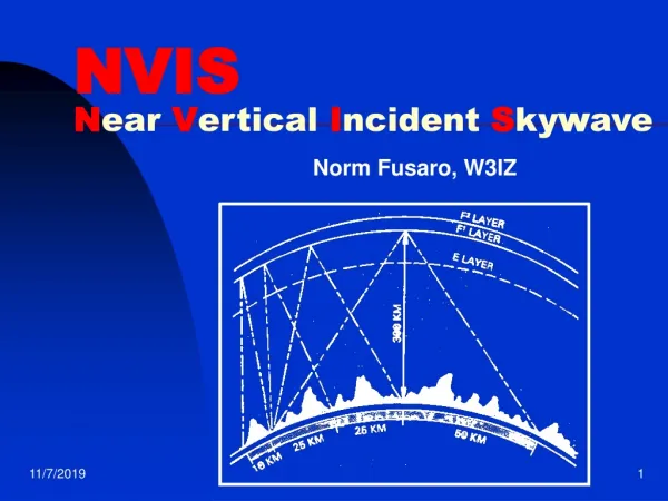
NVIS June 2008
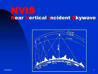
Near Vertical Incident Skywave • A radio propagation mode • An alternate method to obtain reliable communication at distances less than 200 - 300 mi • Uses an antenna with a high radiation angle • Requires use of frequency below “critical” cutoff What is NVIS?
A ground wave signal • Useful on all HF frequencies • Insensitive to propagation conditions • Absolutely reliable What NVIS is Not
NVIS can be a good emergency solution for coverage at distances and circumstances not favorable to VHF • Effective use requires some understanding and planning Why learn about NVIS
Selection of appropriate frequency • Use of an antenna supporting high radiation angle • Sufficient Power • Both ends operating with NVIS antenna • Experienced Operators What helps NVIS to work?
Ionosphere • Sun Induced Ionization • F - Layer • F2 (Reflects at Night) • F1 (Reflects during the Day) • E Layer (Specialized) • D Layer (Daylight) Blocks below 5-6MHz Frequency Selection is based on Propagation Considerations
Critical Frequency • The Critical Frequency is the highest frequency that the ionosphere will reflect vertically • The Critical Frequency is the MUF for NVIS • LUF will be dependent on D layer absorption which is greatest during mid Day • The generality of using 40 meters during the day and 80 meters at night does not always work. Propagation Conditions establish the Critical Frequency
Ionospheric Map http://www.ips.gov.au/Main.php?CatID=6&SecID=4&SecName=North%20America&SubSecID=3&SubSecName=Ionospheric%20Map • This Map can be Used as guide for NVIS frequency Support The map shows that 5 MHz is the highest frequency that will support NVIS in our area at the time the map was created. 20UT = (20-6)= 14 = 2 pm
Ionospheric Map- June 20 10 pm
Frequency Selection Criteria • Critical Frequency sets an upper limit • Use Ionospheric Map to determine MUF • During periods of low/no sun spot activity the critical frequency will be higher • Amount of daylight and distance from the equator is a factor • D-Layer considerations set lower limit Frequency Selection
D-Layer • The D-layer blocks frequencies below about 5 Mhz • The D-layer is less effective at blocking during low/no sun spot activity • Current Conditions • 75/80 meters is the best alternative • 40 meters will be a viable day time alternative as the sun spot cycle progresses Frequency Considerations Cont
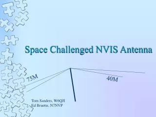
What factors are important to antenna selection • Horizontal polarization • Enhanced vertical radiation • Ground wires needed • Band(s) supported • Space available Antenna Considerations
Low elevation of antenna provides: • Attenuation of low angle dx • Less interference • Attenuation of low angle noise • Lighting and other noise sources • Attenuation of desired signal • Object is greater attenuation of undesired signals than desired signal Reception Considerations
Low elevation will drop the radiation resistance of the antenna • Steps must be taken to match the lower radiation resistance of the antenna • Employ matching methods or consider something like a folded dipole Antenna matching
At least 10 to 15 feet of elevation is desirable (0.05 to 0.1 wavelength) • Matching considerations (possible low Rx) • Good ground conductivity is an asset • Selection of operating frequency (Band) is critical and not always determined by a simple rule of thumb Points to remember
What’s the Deal About “NVIS”, Dec. 2005 QST • Near Vertical Incident Skywave (NVIS) Antenna, Pat Lambert – W0IPL • Near-Vertical Incidence Sky-Wave Propagation Concept, Excerpt for US Army Field Manual 24-18 Appendix M • http://www.ips.gov.au/Main.php?CatID=6&SecID=5&SecName=North% References
Store House 75 meter antenna. Height has now been doubled. Rx low due to proximity to roof
Store House VHF/UHF Antenna TRAM 1480 Gain VHF 144-148 MHz: 6dB UHF 435-450 MHz: 8dB