
Examples
E N D
Presentation Transcript
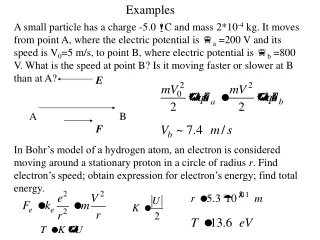
Examples A small particle has a charge -5.0 mC and mass 2*10-4 kg. It moves from point A, where the electric potential is fa =200 V and its speed is V0=5 m/s, to point B, where electric potential is fb =800 V. What is the speed at point B? Is it moving faster or slower at B than at A? E A B F In Bohr’s model of a hydrogen atom, an electron is considered moving around a stationary proton in a circle of radius r. Find electron’s speed; obtain expression for electron’s energy; find total energy.
Calculating Potential from E field • To calculate potential function from E field
When calculating potential due to charge distribution, we calculate potential explicitly if the exact distribution is known. If we know the electric field as a function of position, we integrate the field. Generally, in electrostatics it is easier to calculate a potential (scalar) and then find electric field (vector). In certain situation, Gauss’s law and symmetry consideration allow for direct field calculations. Moreover, if applicable, use energy approach rather than calculating forces directly (dynamic approach) Example: Solid conducting sphere Outside: Potential of the point charge Inside: E=0, V=const
Potential of Charged Isolated Conductor • The excess charge on an isolated conductor will distribute itself so all points of the conductor are the same potential (inside and surface). • The surface charge density (and E) is high where the radius of curvature is small and the surface is convex • At sharp points or edges (and thus external E) may reach high values. • The potential in a cavity in a conductor is the same as the potential throughout the conductor and its surface
At the sharp tip (r tends to zero), large electric field is present even for small charges. Corona – glow of air due to gas discharge near the sharp tip. Voltage breakdown of the air Lightning rod – has blunt end to allow larger charge built-up – higher probability of a lightning strike
Example: Potential between oppositely charged parallel plates From our previous examples Easy way to calculate surface charge density Remember! Zero potential doesn’t mean the conducting object has no charge! We can assign zero potential to any place, only difference in potential makes physical sense
Vb = 0 – not a good choice as it follows Why so? Example: Charged wire We already know E-field around the wire only has a radial component We would want to set Vb = 0 at some distance r0 from the wire r - some distance from the wire
Example: Sphere, uniformly charged inside through volume Q - total charge - volume density of charge This is given that at infinity j =0
Equipotential Surfaces • Equipotential surface—A surface consisting of a continuous distribution of points having the same electric potential • Equipotential surfaces and the E field lines are always perpendicular to each other • No work is done moving charges along an equipotential surface • For a uniform E field the equipotential surfaces are planes • For a point charge the equipotential surfaces are spheres
Equipotential Surfaces Potentials at different points are visualized by equipotential surfaces (just like E-field lines). Just like topographic lines (lines of equal elevations). E-field lines and equipotential surfaces are mutually perpendicular
Potential Gradient On the other hand, we can calculate potential difference directly Components of E in terms of j Frequently, potentials (scalars!) are easier to calculate: So people would calculate potential and then the field Superposition for potentials: V = V1 + V2 + …
Example: A positively charged (+q) metal sphere of radius ra is inside of another metal sphere (-q) of radius rb. Find potential at different points inside and outside of the sphere. -q 1 a) 2 +q Total V=V1+V2 b) c) Electric field between spheres
Grounded conductor φ=const Method of images How to calculate E-field in the vicinity of conducting surface given that there are induced charges on that surface? h Everywhere on the conductive surface Uniqueness theorem in electrostatics : if we know space charge distribution and boundary conditions such as potentials at all conductors, the electric field is uniquely defined in space We can remove the surface and replace it with single point charge –q at a distance h behind the surface. Attractive force between charges
Definitions • Voltage—potential difference between two points in space (or a circuit) • Capacitor—device to store energy as potential energy in an E field • Capacitance—the charge on the plates of a capacitor divided by the potential difference of the plates C = q/V • Farad—unit of capacitance, 1F = 1 C/V. This is a very large unit of capacitance, in practice we use F (10-6) or pF (10-12)
Definitions cont • Electric circuit—a path through which charge can flow • Battery—device maintaining a potential difference V between its terminals by means of an internal electrochemical reaction. • Terminals—points at which charge can enter or leave a battery
Capacitors • A capacitor consists of two conductors called plates which get equal but opposite charges on them • The capacitance of a capacitor C = q/V is a constant of proportionality between q and V and is totally independent of q and V • The capacitance just depends on the geometry of the capacitor, not q and V • To charge a capacitor, it is placed in an electric circuit with a source of potential difference or a battery
CAPACITANCE AND CAPACITORS Capacitor: two conductors separated by insulator and charged by opposite and equal charges (one of the conductors can be at infinity) Used to store charge and electrostatic energy Superposition / Linearity: Fields, potentials and potential differences, or voltages (V), are proportional to charge magnitudes (Q) (all taken positive, V-voltage between plates) CapacitanceC (1 Farad = 1 Coulomb / 1 Volt) is determined by pure geometry (and insulator properties) 1 Farad IS very BIG: Earth’s C < 1 mF
Parallel plate capacitor Energy stored in a capacitor is related to the E-field between the plates Electric energy can be regarded as stored in the field itself. This further suggests that E-field is the separate entity that may exist alongside charges. Generally, we find the potential difference Vab between conductors for a certain charge Q Point charge potential difference ~ Q This is generally true for all capacitances
Capacitance configurations Cylindrical capacitor Spherical Capacitance
Definitions • Equivalent Capacitor—a single capacitor that has the same capacitance as a combination of capacitors. • Parallel Circuit—a circuit in which a potential difference applied across a combination of circuit elements results in the potential difference being applied across each element. • Series Circuit—a circuit in which a potential difference applied across a combination of circuit elements is the sum of the resulting potential differences across each element.
Capacitors in Parallel Example: Voltage before and after
In 1995, the microprocessor unit on the microwave imager on the DMSP F13 spacecraft locked up - occurred ~5 s after spacecraft began to charge up in the auroral zone in an auroral arc. Attributed to high-level charging of spacecraft surface and subsequent discharge.
Spacecraft surfaces are generally covered with thermal blankets - outer layer some dielectric material - typically Kapton or Teflon. Deposition of charge on surface of spacecraft known as surface charging. Incident electrons below about 100 keV penetrate the material to a depth of a few microns, where they form a space charge layer - builds up until breakdown occurs accompanied by material vaporization and ionization. A discharge is initiated - propagates across surface or through the material, removing part of bound charge. Typically occur in holes, seams, cracks, or edges - have been know to seriously damage spacecraft components. Thermal blankets - composed of layers of dieletric material with vapor deposited aluminum (VDA) between each layer. On DMSP, VDA between layers (22) not grounded - serve as plates of a set of 22 parallel-plate capacitors - top plate consists of electrons buried in top few microns of Teflon.
C/A=7.310-9 F/m2 Time to charge outer surface of a parallel plate capacitor to some voltage with respect to spacecraft frame is: Laboratory measurements for Teflon: -discharge at 3 kV in a 20 keV electron beam -secondary electron yield () at 20 keV ~ 0.2 Given measured incident precipitating current density of i = 4.8 A/m2, the time to reach breakdown voltage for conditions experienced by DMSP F13 is 5.7 s - this is the time after the spacecraft began to charge up that the lockup occurred. If the VDA layer on the bottom side of the outer Teflon layer were grounded to the spacecraft frame, the capacitance would have been 3.510-7 F/m2 and the charging time would have been 132 s - no discharge would have occurred.