Download
1 / 62
630 likes | 816 Views
Triggering CMS. Wesley H. Smith U. Wisconsin – Madison CMS Trigger Coordinator Seminar, Texas A&M April 20, 2011 Outline: Introduction to CMS Trigger Challenges & Architecture Level -1 Trigger Implementation & Performance Higher Level Trigger Algorithms & Performance

E N D
Triggering CMS Wesley H. Smith U. Wisconsin – Madison CMS Trigger Coordinator Seminar, Texas A&M April 20, 2011 • Outline: • Introduction to CMS • Trigger Challenges & Architecture • Level -1 Trigger Implementation & Performance • Higher Level Trigger Algorithms & Performance • The Future: SLHC Trigger
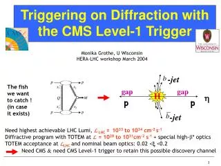
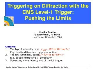
LHC Collisions with every bunch crossing 23 Minimum Bias events with ~1725 particles produced
LHC Physics & Event Rates • At design L = 1034cm-2s-1 • 23 pp events/25 ns xing • ~ 1 GHz input rate • “Good” events contain ~ 20 bkg. events • 1 kHz W events • 10 Hz top events • < 104 detectable Higgs decays/year • Can store ~ 300 Hz events • Select in stages • Level-1 Triggers • 1 GHz to 100 kHz • High Level Triggers • 100 kHz to 300 Hz
Operating conditions: one “good” event (e.g Higgs in 4 muons ) + ~20 minimum bias events) All charged tracks with pt > 2 GeV Reconstructed tracks with pt > 25 GeV Collisions (p-p) at LHC Event rate Event size: ~1 MByte Processing Power: ~X TFlop
CMS Detector Design CALORIMETERS Superconducting Coil,4 Tesla HCAL ECAL Plastic scintillator/brass sandwich 76k scintillating PbWO4 crystals IRON YOKE • Level-1 Trigger Output • Today: 50 kHz(instead of 100) TRACKER Today:RPC |η| < 1.6 instead of 2.1 & 4th endcap layer missing PixelsSilicon Microstrips 210 m2 of silicon sensors 9.6M channels MUON ENDCAPS MUON BARREL Cathode Strip Chambers (CSC) Resistive Plate Drift Tube Resistive Plate Chambers (RPC) Chambers (RPC) Chambers (DT)
LHC Trigger & DAQ Challenges Challenges: 1 GHz of Input Interactions Beam-crossing every 25 ns with ~ 23 interactions produces over 1 MB of data Archival Storage at about 300 Hz of 1 MB events 40 MHz 16 Million channels DETECTOR CHANNELS COLLISION RATE 3 Gigacell buffers LEVEL-1 TRIGGER Charge Time Pattern Energy Tracks 1 MB EVENT DATA 100 - 50 kHz 1 Terabit/s 200 GB buffers READOUT ~ 400 Readout memories 50,000 data channels EVENT BUILDER. A large switching network (400+400 ports) with total throughput ~ 400Gbit/s forms the interconnection between the sources (deep buffers) and the destinations (buffers before farm CPUs). 500 Gigabit/s SWITCH NETWORK ~ 400 CPU farms EVENT FILTER. A set of high performance commercial processors organized into many farms convenient for on-line and off-line applications. 300 Hz FILTERED 5 TeraIPS EVENT Computing Services Gigabit/s Petabyte ARCHIVE SERVICE LAN
L1 Trigger Locations • Underground Counting Room • Central rows of racks fortrigger • Connections via high-speed copper links to adjacent rows of ECAL & HCAL readout racks with trigger primitive circuitry • Connections via opticalfiber to muon trigger primitive generatorson the detector • Optical fibersconnected via“tunnels” to detector(~90m fiber lengths) 7m thickshieldingwall USC55 Rows of Racks containing trigger & readout electronics
CMS Level-1 Trigger & DAQ • Overall Trigger & DAQ Architecture: 2 Levels: • Level-1 Trigger: • 25 ns input • 3.2 μs latency UXC USC Interaction rate: 1 GHz Bunch Crossing rate: 40 MHz Level 1 Output: 100 kHz (50 initial) Output to Storage: 100 Hz Average Event Size: 1 MB Data production 1 TB/day
CMS Calorimeter Geometry Trigger towers:Δη = Δϕ = 0.087 EB, EE, HB, HE map to 18 RCT crates Provide e/γ and jet, τ, ET triggers 2 HF calorimeters map on to 18 RCT crates 1 trigger tower (.087η✕ .087φ) = 5 ✕ 5 ECAL xtals = 1 HCAL tower
ECAL Endcap Geometry • Map non-projective x-y trigger crystal geometry onto projective trigger towers: Individualcrystal +Z Endcap -Z Endcap 5 x 5 ECAL xtals ≠ 1 HCAL tower in detail
Calorimeter Trig. Processing OD TTC TCS Trigger Tower 25 Xtals (TT) Level 1 Trigger (L1A) L1 @100 kHz CCS (CERN) Regional CaloTRIGGER SLB (LIP) TCC (LLR) Global TRIGGER Trigger Tower Flags (TTF) Trigger primitives @800 Mbits/s Trigger Concentrator Card Synchronisation & Link Board Clock & Control System Selective Readout Processor Data Concentrator Card Timing, Trigger & Control Trigger Control System SRP (CEA DAPNIA) Selective Readout Flags (SRF) Data path @100KHz (Xtal Datas) DAQ DCC (LIP) From : R. Alemany LIP
Calorimeter Trig.Overview(located in underground counting room) Copper 80 MHz Parallel 4 Highest ET: Isolated & non-isol. e/γ Central, forward, τ jets, Ex, Ey from each crate 4K 1.2 Gbaud serial links w/ 2 x (8 bits E/H/FCAL Energy + fine grain structure bit) + 5 bits error detection code per 25 ns crossing Lumi- nosity Info. US CMS: Wisconsin Bristol/CERN/Imperial/LANL US CMS HCAL: BU/FNAL/ Maryland/ Princeton Global Cal. Trigger Sorting, ETMiss, ΣET Regional Calorimeter Trigger Receiver Electron Isolation Jet/Summary GCT Matrixμ + Q bits Calorimeter Electronics Interface Global Trigger Processor IC/LANL/UW CMS: Vienna CMS ECAL: Lisbon/ Palaiseau 72 φ✕ 60 η H/ECAL Towers (.087φ ✕ .087η for η < 2.2 & .174-.195η, η>2.2) HF: 2✕(12 φ✕ 12 η) Global Muon Trigger Iso Mu MinIon Tag MinIon & Quiet Tags for each 4φ✕ 4η region
ECAL Trigger Primitives Test beam results (45 MeV per xtal):
Sample of min bias events, triggered by BSC coincidence, with good vertex and no scraping Fraction of candidates that are in time with bunch-crossing (BPTX) trigger as function of L1 assigned ET Anomalous signals from ECAL, HF removed Noise pollutes BX ID efficiency at low ET values L1 Cal. Trigger SynchronizationBX ID Efficiency – e/γ& Jets e/γ Jet/τ Forward Jet
L1 efficiency for electrons • Sample of ECAL Activity HLT triggers (seeded by L1 ZeroBias) • Anomalous ECAL signals removed using standard cuts • EG trigger efficiency for electrons from conversions • Standard loose electron isolation & ID • Conversion ID (inverse of conversion rejection cuts) to select electron-like objects • Efficiency shown w.r.t ET of the electron supercluster, for L1 threshold of 5 GeV (top), 8 GeV (bottom) • Two η ranges shown: • Barrel (black), endcaps (red) L1_EG5 With RCT Correction L1_EG8
Jet Trigger Efficiency • minimum-bias trigger • jet energy correction: online / offline match • turn-on curves steeper
MB4 MB3 MB2 MB1 CMS Muon Chambers Single Layer Reduced RE system |η| < 1.6 1.6 *RPC *Double Layer ME4/1 ME3 ME2 ME1
Muon Trigger Overview |η| < 1.2 0.8 < |η| |η| < 2.4 |η| < 2.1 |η| < 1.6 in 2009 Cavern: UXC55 Counting Room: USC55
CMS Muon Trigger Primitives Memory to store patterns Fast logic for matching FPGAs are ideal
CMS Muon TriggerTrack Finders Memory to store patterns Fast logic for matching FPGAs are ideal Sort based on PT, Quality - keep loc. Combine at next level - match Sort again - Isolate? Top 4 highest PT and quality muons with location coord. Match with RPC Improve efficiency and quality
L1 Muon Trigger SynchronizationBX ID Efficiency – CSC, DT, RPC • All muon trigger timing within ± 2 ns, most better & being improved CSC RPC DT Log Plot
L1 Muon Efficiency vs. pT EndCap Barrel L1_Mu7 L1_Mu10 L1_Mu12 L1_Mu20 OverLap
“Δelta” or “correlation” conditions • Unique Topological Capability of CMS L1 Trigger • separate objects in η & Φ: • Δ ≥ 2 hardware indices • ϕ: Δ ≥ 20 .. 40 degrees • Present Use: • eγ / jet separation to avoid triggering twice on the same object in a correlation trigger • objects to be separated by one empty sector (20 degrees)
High-Level Trig. Implementation 8 “slices” All processing beyond Level-1 performed in the Filter Farm Partial event reconstruction “on demand” using full detector resolution
Start with L1 Trigger Objects • Electrons, Photons, τ-jets, Jets, Missing ET, Muons • HLT refines L1 objects (no volunteers) • Goal • Keep L1T thresholds for electro-weak symmetry breaking physics • However, reduce the dominant QCD background • From 100 kHz down to 100 Hz nominally • QCD background reduction • Fake reduction: e±, γ, τ • Improved resolution and isolation: μ • Exploit event topology: Jets • Association with other objects: Missing ET • Sophisticated algorithms necessary • Full reconstruction of the objects • Due to time constraints we avoid full reconstruction of the event - L1 seeded reconstruction of the objects only • Full reconstruction only for the HLT passed events
super-cluster basic cluster Electron & Photon HLT • “Level-2” electron: • Search for match to Level-1 trigger • 1-tower margin around 4x4-tower trig. region • Bremsstrahlung recovery “super-clustering” • Road along φ— in narrow η-window around seed • Collect all sub-clusters in road η “super-cluster” • Select highest ET cluster • Calorimetric (ECAL+HCAL) isolation • “Level-3” Photons • Tight track isolation • “Level-3” Electrons • Electron track reconstruction • Spatial matching of ECAL cluster • and pixel track • Loose track isolation ina “hollow” cone
“Tag & probe” HLT Electron Efficiency • Use Z mass resonance to select electron pairs & probe efficiency of selection • Tag: lepton passing very tight selection with very low fake rate (<<1%) • Probe: lepton passing softer selection & pairing with Tag object such that invariant mass of tag & probe combination is consistent with Z resonance • Efficiency = Npass/Nall • Npass → number of probes passing the selection criteria • Nall → total number of probes counted using the resonance Electron (ET Thresh>17 GeV) with Tighter Calorimeter-basedElectron ID+Isolation at HLT The efficiency of electron trigger paths in 2010 data reaches 100% within errors Barrel Endcap
Muon HLT & L1 Efficiency • Both isolated & non-isolated muon trigger shown • Efficiency loss is at Level-1, mostly at high-η • Improvement over these curves already done • Optimization of DT/CSC overlap & high-η regions
Jet HLT Efficiency • Jet efficiencies calculated • Relative to a lower threshold trigger • Relative to an independent trigger • Jet efficiencies plotted vs. corrected offline reco • Anti-kTjet energy • Plots are from 2011 run 161312 HLT_Jet240 HLT_Jet370 Barrel Endcap All Barrel Endcap All
Photon Photons (no had. requirement) MuEG Mu+photon or ele (no had. requirement) ElectronHad electrons + had. activity PhotonHad Photons + had. activity MuHad Muons + had. activity Tau Single and Double taus TauPlusX X-triggers with taus MuOnia J/psi, upsilon Summary of Current Physics Menu(5E32) by Primary Dataset • Jet • Single Jet, DiJetAve,MultiJet • QuadJet, ForwardJets, Jets+Taus • HT • Misc. hadronic SUSY triggers • METBtag • MET triggers, Btag POG triggers • SingleMu • Single mu triggers (no had. requirement) • DoubleMu • Double mu trigger (no had. requirement) • SingleElectron • Single e triggers (no had. requirement) • DoubleElectron • Double e triggers (no had requirement) + Commisioning, Cosmics, MinimumBias Expected rate of each PD is 15-30 Hz @ 5E32 Writing a total of O(360) Hz. (Baseline is 300 Hz)
Trigger Rates in 2011 • Trigger rate predictions based mostly on data. • Emulation of paths via OpenHLT working well for most of trigger table • Data collected already w/ sizeable PU (L=2.5E32 → PU~7) • Allows linear extrapolation to higher luminosity scenarios • Emulated & • Online Rates: Agreement to ≲ 30%, data-only check of measured ratevs. separate emulation
Approx. evolution for some triggers • L=5E32 • Single Iso Mu ET: 17 GeV • Single Isoelec ET: 27 GeV • Double Mu ET: 6, 6 GeV • Double Elec ET: 17, 8 GeV • e+mu ET: 17,8 & 8,17 GeV • Di-photon: 26, 18 GeV • e/mu + tau: 15, 20 GeV • HT: 440 GeV • HT+MHT: 520 GeV • L=2E33 • Single Iso Mu ET: 30 GeV • Single Isoelec ET: 50 GeV • Double Mu ET: 10,10 GeV • Double Elec ET: 17, 8 GeV* • e+mu ET: 17,8 & 8,17 GeV* • Di-photon: 26, 18 GeV* • e/mu + tau: 20, 20-25 GeV • HT: • HT+MHT: Possibly large uncertainty due to pile-up Targeted rate of each line is ~10-15 Hz. Overall menu has many cross triggers for signal and prescaled triggers for efficiencies and fake rate measurements as well * Tighter ID and Iso conditions, still rate and/or efficiency concerns
HLT at 1E33 • Total is 400 Hz
Total HLT Time Distribution Prescale set used: 2E32 Hz/cm² Sample: MinBias L1-skim 5E32 Hz/cm² with 10 Pile-up Unpacking of L1 information, early-rejection triggers,non-intensivetriggers Mostly unpacking of calorimeter info. to form jets, & some muon triggers Triggers with intensive tracking algorithms Overflow: Triggers doing particle flow reconstruction (esp. taus)
Phase 1: Goal of extended running in second half of the decade to collect ~100s/fb 80% of this luminosity in the last three years of this decade About half the luminosity would be delivered at luminosities above the original LHC design luminosity Trigger & DAQ systems should be able to operate with a peak luminosity of up to 2 x 1034 Phase 2: Continued operation of the LHC beyond a few 100/fb will require substantial modification of detector elements The goal is to achieve 3000/fb in phase 2 Need to be able to integrate ~300/fb-yr Will require new tracking detectors for ATLAS & CMS Trigger & DAQ systems should be able to operate with a peak luminosity of up to 5 x 1034 Requirements for LHC phases of the upgrades: ~2010-2020
Detector Luminosity Effects • H→ZZ → μμee, MH= 300 GeV for different luminosities in CMS 1032 cm-2s-1 1033 cm-2s-1 1034 cm-2s-1 1035 cm-2s-1
CMS Upgrade Trigger Strategy • Constraints • Output rate at 100 kHz • Input rate increases x2/x10 (Phase 1/Phase 2) over LHC design (1034) • Same x2 if crossing freq/2, e.g. 25 ns spacing → 50 ns at 1034 • Number of interactions in a crossing (Pileup) goes up by x4/x20 • Thresholds remain ~ same as physics interest does • Example: strategy for Phase 1 Calorimeter Trigger (operating 2016+): • Present L1 algorithms inadequate above 1034 or 1034 w/ 50 ns spacing • Pileup degrades object isolation • More sophisticated clustering & isolation deal w/more busy events • Process with full granularity of calorimeter trigger information • Should suffice for x2 reduction in rate as shown with initial L1 Trigger studies & CMS HLT studies with L2 algorithms • Potential new handles at L1 needed for x10 (Phase 2: 2020+) • Tracking to eliminate fakes, use track isolation. • Vertexing to ensure that multiple trigger objects come from same interaction • Requires finer position resolution for calorimeter trigger objects for matching (provided by use of full granularity cal. trig. info.)
Phase 1 Upgrade Cal. Trigger Algorithm Development Particle Cluster Finder Applies tower thresholds to Calorimeter Creates overlapped 2x2 clusters Cluster Overlap Filter Removes overlap between clusters Identifies local maxima Prunes low energy clusters Cluster Isolation and Particle ID Applied to local maxima Calculates isolation deposits around 2x2,2x3 clusters Identifies particles Jet reconstruction Applied on filtered clusters Groups clusters to jets Particle Sorter Sorts particles & outputs the most energetic ones MET,HT,MHT Calculation Calculates Et Sums, Missing Et from clusters HCAL ΔηxΔφ=0.087x0.087 η ECAL φ e/γ HCAL η ECAL φ τ HCAL η ECAL φ jet
Upgrade Algorithm Performance:Factor of 2 for Phase I Present Algorithm Present Algorithm Isolated electrons Taus QCD Rate (kHz) QCD Rate (kHz) Phase 1 Algorithm Phase 1 Algorithm Factor of 2 rate reduction Phase 1 Algorithm Phase 1 Algorithm Isolated electrons Taus Efficiency Efficiency Present Algorithm Present Algorithm Higher Efficiency
uTCA Calorimeter Trigger Demonstrators • processing cards with 160 Gb/s input & 100 Gb/s output using 5 Gb/s optical links. • four trigger prototype cards integrated in a backplane fabric to demonstrate running & data exchange of calorimeter trigger algorithms
CMS CSC Trigger Upgrades • Improve redundancy • Add station ME-4/2 covering h=1.1-1.8 • Critical for momentum resolution • Upgrade electronics to sustain higher rates • New Front End boards for station ME-1/1 • Forces upgrade of downstream EMU electronics • Particularly Trigger & DAQ Mother Boards • Upgrade Muon Port Card and CSC Track Finder to handle higher stub rate • Extend CSC Efficiency into h=2.1-2.4 region • Robust operation requires TMB upgrade, unganging strips in ME-1a, new FEBs, upgrade CSCTF+MPC ME4/2