Understanding Network Layer Routing: Concepts and Algorithms
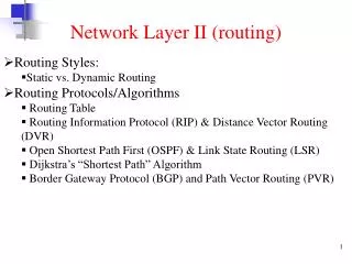
This lecture explores the Network Layer's role in computer communications, focusing on routing activities. It covers critical concepts such as IP addressing, longest prefix matching, subnets, and CIDR (Classless Inter-Domain Routing). The content details hierarchical addressing, route aggregation, and the dynamics between routing and forwarding. Key algorithms such as Distance Vector and Link State Routing, including RIP and OSPF, are examined to illustrate the principles of network routing. Essential for students in computer science and engineering, this material provides foundational knowledge for effective network management.

Understanding Network Layer Routing: Concepts and Algorithms
E N D
Presentation Transcript
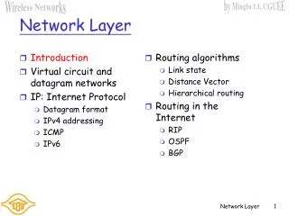
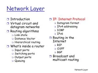
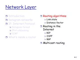
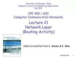
University of Nevada – Reno Computer Science & Engineering Department Fall 2011 CPE 400 / 600Computer Communication Networks Lecture 21 Network Layer (Routing Activity) slides are modified from J. Kurose & K. Ross Introduction
Longest prefix matching Prefix MatchLink Interface 11001000 00010111 00010 0 11001000 00010111 00011000 1 11001000 00010111 00011 2 otherwise 3 Examples Which interface? DA: 11001000 00010111 00010110 10100001 Which interface? DA: 11001000 00010111 00011000 10101010 Network Layer
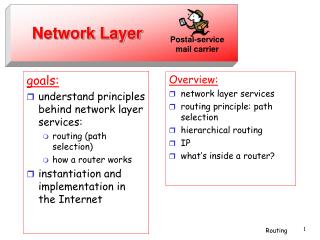
IP address: 32-bit identifier for host, router interface interface: connection between host/router and physical link router’s typically have multiple interfaces host typically has one interface IP addresses associated with each interface 223.1.1.2 223.1.2.2 223.1.2.1 223.1.3.2 223.1.3.1 223.1.3.27 IP Addressing: introduction 223.1.1.1 223.1.2.9 223.1.1.4 223.1.1.3 223.1.1.1 = 11011111 00000001 00000001 00000001 223 1 1 1 Network Layer
IP address: subnet part high order bits host part low order bits What’s a subnet ? device interfaces with same subnet part of IP address can physically reach each other without intervening router Subnets 223.1.1.1 223.1.2.1 223.1.1.2 223.1.2.9 223.1.1.4 223.1.2.2 223.1.1.3 223.1.3.27 subnet 223.1.3.2 223.1.3.1 network consisting of 3 subnets Network Layer
host part subnet part 11001000 0001011100010000 00000000 200.23.16.0/23 IP addressing: CIDR CIDR:Classless InterDomainRouting • subnet portion of address of arbitrary length • address format: a.b.c.d/x • where x is # bits in subnet portion of address Network Layer
200.23.16.0/23 200.23.18.0/23 200.23.30.0/23 200.23.20.0/23 . . . . . . Hierarchical addressing: route aggregation & more specific routes Hierarchical addressing allows efficient advertisement of routing information: Organization 0 “Send me anything with addresses beginning 200.23.16.0/20” Organization 2 Fly-By-Night-ISP Internet Organization 7 “Send me anything with addresses beginning 199.31.0.0/16 or 200.23.18.0/23” ISPs-R-Us Organization 1 ISPs-R-Us has a more specific route to Organization 1 Network Layer
routing algorithm local forwarding table header value output link 0100 0101 0111 1001 3 2 2 1 value in arriving packet’s header 1 0111 2 3 Interplay between routing, forwarding Network Layer
RIPDistance Vector Algorithm Transport Layer
Distance Vector Algorithm Bellman-Ford Equation (dynamic programming) Define dx(y) := cost of least-cost path from x to y Then dx(y) = min {c(x,v) + dv(y) } where min is taken over all neighbors v of x v Network Layer
5 3 5 2 2 1 3 1 2 1 x z w u y v Bellman-Ford example Clearly, dv(z) = 5, dx(z) = 3, dw(z) = 3 B-F equation says: du(z) = min { c(u,v) + dv(z), c(u,x) + dx(z), c(u,w) + dw(z) } = min {2 + 5, 1 + 3, 5 + 3} = 4 Node that achieves minimum is next hop in shortest path ➜ forwarding table Network Layer
Distance Vector Algorithm • Dx(y) = estimate of least cost from x to y • Node x knows cost to each neighbor v: c(x,v) • Node x maintains distance vector Dx = [Dx(y): y є N ] • Node x also maintains its neighbors’ distance vectors • For each neighbor v, x maintains Dv = [Dv(y): y є N ] Network Layer
Iterative, asynchronous: each local iteration caused by: local link cost change DV update message from neighbor Distributed: each node notifies neighbors only when its DV changes neighbors then notify their neighbors if necessary wait for (change in local link cost or msg from neighbor) recompute estimates if DV to any dest has changed, notify neighbors Distance Vector Algorithm Each node: Network Layer
cost to x y z x 0 2 7 y from ∞ ∞ ∞ z ∞ ∞ ∞ 2 1 7 z x y Dx(z) = min{c(x,y) + Dy(z), c(x,z) + Dz(z)} = min{2+1 , 7+0} = 3 Dx(y) = min{c(x,y) + Dy(y), c(x,z) + Dz(y)} = min{2+0 , 7+1} = 2 node x table cost to cost to x y z x y z x 0 2 3 x 0 2 3 y from 2 0 1 y from 2 0 1 z 7 1 0 z 3 1 0 node y table cost to cost to cost to x y z x y z x y z x ∞ x 0 2 7 ∞ ∞ 2 0 1 x 0 2 3 y y from 2 0 1 y from from 2 0 1 z z ∞ ∞ ∞ 7 1 0 z 3 1 0 node z table cost to cost to cost to x y z x y z x y z x 0 2 7 x 0 2 3 x ∞ ∞ ∞ y y 2 0 1 from from y 2 0 1 from ∞ ∞ ∞ z z z 3 1 0 3 1 0 7 1 0 time Network Layer
u v destinationhops u 1 v 2 w 2 x 3 y 3 z 2 w x z y C A D B RIP (Routing Information Protocol) • distance metric: # of hops (max = 15 hops) • distance vectors: exchanged among neighbors every 30 sec via Response Message • also called advertisement • each advertisement: list of up to 25 destination subnets within AS From router A to subnets: Network Layer
z y w x A D B C RIP: Example Dest Next hops w - 1 x - 1 z C 4 …. … ... New Advertisement from A to D Destination Network Next Router Num. of hops to dest. w A 2 y B 2 z B A 7 5 x -- 1 …. …. .... Routing/Forwarding table in D Network Layer
OSPFLink State Routing Algorithm Transport Layer
Dijkstra’s algorithm net topology, link costs known to all nodes accomplished via “link state broadcast” all nodes have same info computes least cost paths from one node (‘source”) to all other nodes gives forwarding table for that node iterative: after k iterations, know least cost path to k dest.’s Notation: c(x,y): link cost from node x to y; = ∞ if not direct neighbors D(v): current value of cost of path from source to dest. v p(v): predecessor node along path from source to v N': set of nodes whose least cost path definitively known A Link-State Routing Algorithm Network Layer
Dijsktra’s Algorithm 1 Initialization: 2 N' = {u} 3 for all nodes v 4 if v adjacent to u 5 then D(v) = c(u,v) 6 else D(v) = ∞ 7 8 Loop 9 find w not in N' such that D(w) is a minimum 10 add w to N' 11 update D(v) for all v adjacent to w and not in N' : 12 D(v) = min( D(v), D(w) + c(w,v) ) 13 /* new cost to v is either old cost to v or known 14 shortest path cost to w plus cost from w to v */ 15 until all nodes in N' Network Layer
5 3 5 2 2 1 3 1 2 1 x z w u y v destination link (u,v) v (u,x) x y (u,x) (u,x) w z (u,x) Dijkstra’s algorithm: example D(v),p(v) 2,u 2,u 2,u D(x),p(x) 1,u D(w),p(w) 5,u 4,x 3,y 3,y D(y),p(y) ∞ 2,x Step 0 1 2 3 4 5 N' u ux uxy uxyv uxyvw uxyvwz D(z),p(z) ∞ ∞ 4,y 4,y 4,y Resulting forwarding table in u: Network Layer
OSPF (Open Shortest Path First) • “open”: publicly available • uses Link State algorithm • LS packet dissemination • topology map at each node • route computation using Dijkstra’s algorithm • OSPF advertisement carries one entry per neighbor router • advertisements disseminated to entire AS (via flooding) • OSPF messages directly over IP (rather than TCP or UDP) Network Layer
OSPF “advanced” features (not in RIP) • security: all OSPF messages authenticated • to prevent malicious intrusion • multiple same-cost paths allowed • only one path in RIP • For each link, multiple cost metrics for different TOS • e.g., satellite link cost set “low” for best effort; high for real time • integrated uni- and multicast support: • Multicast OSPF (MOSPF) uses same topology data base as OSPF • hierarchical OSPF in large domains Network Layer
Hierarchical OSPF Network Layer
Hierarchical OSPF • two-level hierarchy: local area, backbone • Link-state advertisements only in area • each nodes has detailed area topology • only know direction (shortest path) to nets in other areas • area border routers:“summarize” distances to nets in own area, advertise to other Area Border routers • backbone routers: run OSPF routing limited to backbone • boundary routers: connect to other AS’s Network Layer
BGPHierarchical Routing Transport Layer
aggregate routers into regions, “Autonomous Systems” (AS) routers in same AS run same routing protocol “intra-AS” routing protocol routers in different AS can run different intra-AS routing protocol Gateway router Direct link to router in another AS Hierarchical Routing Network Layer
forwarding table configured by both intra- and inter-AS routing algorithm intra-AS sets entries for internal dests inter-AS & intra-As sets entries for external dests 2c 2b 3c 1b 1d 1c Inter-AS Routing algorithm Intra-AS Routing algorithm Interconnected ASes 3a 3b 2a AS3 AS2 1a AS1 Forwarding table Network Layer
2c 2b 3c 1b 1d 1c Example: Setting forwarding table in router 1d • suppose AS1 learns (via inter-AS protocol) that subnet x reachable via AS3 (gateway 1c) but not via AS2. • inter-AS protocol propagates reachability info to all internal routers. • router 1d determines from intra-AS routing info that its interface I is on the least cost path to 1c. • installs forwarding table entry (x,I) … x 3a 3b 2a AS3 AS2 1a AS1 Network Layer
2c 2b 3c 1b 1d 1c BGP basics • pairs of routers (BGP peers) exchange routing info over semi-permanent TCP connections: BGP sessions • BGP sessions need not correspond to physical links • when AS2 advertises a prefix to AS1: • AS2 promises it will forward datagrams towards that prefix • AS2 can aggregate prefixes in its advertisement eBGP session iBGP session 3a 3b 2a AS3 AS2 1a AS1 Network Layer
2c 2b 3c 1b 1d 1c Distributing reachability info • using eBGP session between 3a and 1c, AS3 sends prefix reachability info to AS1 • 1c can then use iBGP do distribute new prefix info to all routers in AS1 • 1b can then re-advertise new reachability info to AS2 over 1b-to-2a eBGP session • when router learns of new prefix, it creates entry for prefix in its forwarding table eBGP session iBGP session 3a 3b 2a AS3 AS2 1a AS1 Network Layer
legend: provider B network X W A customer network C Y BGP routing policy • A,B,C are provider networks • X,W,Y are customer (of provider networks) • X is dual-homed: attached to two networks • X does not want to route from B via X to C • A advertises path AW to B • B advertises path BAW to X • B noes not advertise path BAW to C? • B gets no “revenue” since neither W nor C are B’s customers • B wants to force C to route to w via A • B wants to route only to/from its customers! Network Layer