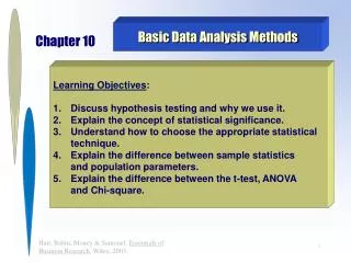
Mastering Basic Circuit Analysis Methods
Learn the fundamentals of circuit analysis including equivalent circuits, nodal, and mesh analysis techniques with practical examples and step-by-step guidance.

Mastering Basic Circuit Analysis Methods
E N D
Presentation Transcript
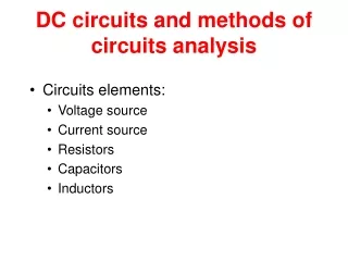
Engineering Circuit Analysis Ch2 Basic Analysis Methods to Circuits 2.1Equivalent Circuits 2.2 Basic Nodal and Mesh Analysis 2.3Useful Circuit Analysis Techniques References: Hayt-Ch3, 4; Gao-Ch2;
Ch2 Basic Analysis Methods to Circuits 2.1Equivalent Circuits Key Words: Equivalent Circuits Network Equivalent Resistance, Equivalent IndependentSources
о Two-terminal Circuits Network c о d о о a о 5 6 15 5 b о I a I a N2 N1 о о + + V V _ о о b b о о о о Ch2 Basic Analysis Methods to Circuits 2.1Equivalent Circuits Equivalent Circuits Network
+ I1 I2 I I1 + I2 = I R1 R2 V - Ch2 Basic Analysis Methods to Circuits 2.1Equivalent Circuits How do we find I1 and I2? Equivalent Resistance
i(t) i(t) + + v(t) v(t) Req - - Ch2 Basic Analysis Methods to Circuits 2.1Equivalent Circuits Equivalent Resistance Req is equivalent to the resistor network on the left in the sense that they have the same i-v characteristics.
Method 1 Series and parallel Resistance (source-free) a I Method 2 source -free V = = R R V o ab I b Method 3 source source Isc Voc Ch2 Basic Analysis Methods to Circuits 2.1Equivalent Circuits Equivalent Resistance Condition : without knowing V&I . We only know Rs Condition : without knowing Rs. We only know V&I
IL(A) , Short Circuit (SC) . 100 , Open Circuit (OC) . 0 10 VL(V) Ch2 Basic Analysis Methods to Circuits 2.1Equivalent Circuits Equivalent Resistance In practice , Vs-source voltage ≠ VL- Local Let The IL-VL curve:
Method 1 Method 3 a R2 R3 R1 VS b a I R2 R3 R1 V b Ch2 Basic Analysis Methods to Circuits 2.1Equivalent Circuits How do we find Rab? Equivalent Resistance P2.1 + - Method 2
Ch2 Basic Analysis Methods to Circuits 2.1Equivalent Circuits • Ideally: • An ideal current source has the voltage necessary to provide its rated current • An ideal voltage source supplies the current necessary to provide its rated voltage • Practice: • A real voltage source cannot supply arbitrarily large amounts of current • A real current source cannot have an arbitrarily large terminal voltage Source Transformation
Rs + Vs - Ch2 Basic Analysis Methods to Circuits 2.1Equivalent Circuits Source Transformation Is Rs Note: Consistency between the current source ref. direction and the voltage Source ref. terminals.
+ I1 I2 Is1 Is2 R1 R2 V - Ieq Ch2 Basic Analysis Methods to Circuits 2.1Equivalent Circuits How do we find I1 and I2? Equivalent Source
parallel Current Source RS=RS1// RS2//…// RSn - VS1 VS2 + VS - - + + VSn - + I IS ISn IS1 IS2 Ch2 Basic Analysis Methods to Circuits 2.1Equivalent Circuits Equivalent Source Series Voltage Source
Ch2 Basic Analysis Methods to Circuits 2.2 Basic Nodal and Mesh Analysis • Why? • The analysis techniques previously (voltage divider, equivalent resistance, etc.) provide an intuitive approach to analyzing circuits • They are not systematic and cannot be easily automated by a computer • Comments: • Analysis of circuits using node or loop analysis requires solutions of systems of linear equations. • These equations can usually be written by inspection of the circuit. Key Words: Branch Analysis,Nodal Analysis, Mesh (Loop) Analysis
I2 I3 I1 Ch2 Basic Analysis Methods to Circuits 2.2 Basic Nodal and Mesh Analysis Branch Analysis P2.2 How do we find I1 and I2, I3? KVL Mesh 1: Mesh 2: KCL
Suppose m branches, n nodals Ch2 Basic Analysis Methods to Circuits 2.2 Basic Nodal and Mesh Analysis Branch Analysis • write KCL equation for each independent node. ——(n-1) KCL equations • write KVL equation for each independent mesh/loop ——m-(n-1) KVL equations
Ch2 Basic Analysis Methods to Circuits 2.2 Basic Nodal and Mesh Analysis Branch Analysis Here’s a quick example of a circuit that we will see later when we model the operation of transistors. For now, let’s assume ideal independent and dependent sources. Ⅰ We can write the following equations: Ⅰ: Ⅱ: Ⅲ : Ⅱ Ⅲ
500W 500W + I1 V 1kW 500W I2 500W - Ch2 Basic Analysis Methods to Circuits 2.2 Basic Nodal and Mesh Analysis The reference node is called the ground node. Nodal Analysis 1) Choose a reference node
500W 500W + I7 I4 I1 V 1kW 500W I2 I6 I5 I8 500W - Ⅰ: Ⅱ: Ch2 Basic Analysis Methods to Circuits 2.2 Basic Nodal and Mesh Analysis 0 Nodal Analysis 1) Choose a reference node . . . Ⅰ Ⅱ Ⅲ KCL Ⅲ :
500W 500W V1 V2 V3 1 2 3 I7 I4 I1 1kW 500W I2 I6 I5 I8 500W Ch2 Basic Analysis Methods to Circuits 2.2 Basic Nodal and Mesh Analysis V1, V2, and V3 are unknowns for which we solve using KCL. Nodal Analysis 2) Assign node voltages to the other nodes 0
500W 500W V1 V2 V3 1 2 3 I7 I4 I1 1kW 500W I2 I6 I5 I8 500W KCL • Node ① : • Node ② : • Node ③ : Node ①: Node ②: , , Node ③: , , Ch2 Basic Analysis Methods to Circuits 2.2 Basic Nodal and Mesh Analysis Nodal Analysis 3) Apply KCL to each node other than the reference-express currents in terms of node voltages. 0
V1 V2 500W V3 500W 1 2 3 I1 1kW I2 500W 500W Ch2 Basic Analysis Methods to Circuits 2.2 Basic Nodal and Mesh Analysis Nodal Analysis 4) Solve the resulting system of linear equations. • Node 1: • Node 2: • Node 3: 0 • The left hand side of the equation: • The node voltage is multiplied by the sum of conductances of all resistors connected to the node. • The neighbourly node voltages are multiplied by the conductance of the resistor(s) connecting to the two nodes and to be subtracted. • The right hand side of the equation: • The right side of the equation is the sum of currents from sources entering the node.
V1 V2 500W V3 500W 1 2 3 I1 1kW I2 500W 500W Matrix Notation(Symmetric) Ch2 Basic Analysis Methods to Circuits 2.2 Basic Nodal and Mesh Analysis Nodal Analysis 4) Solve the resulting system of linear equations. • Node 1: • Node 2: • Node 3:
V1 V2 500W V3 500W 1 2 3 I1 1kW I2 500W 500W G11V1+G12V2 +G13V3 =I11 G21V2+G22V2 +G23V3=I22 G31V1+G32V2+G33V3=I33 Ch2 Basic Analysis Methods to Circuits 2.2 Basic Nodal and Mesh Analysis Nodal Analysis 4) Solve the resulting system of linear equations. • Node 1: • Node 2: • Node 3:
V2 V1 1 2 Ib + 1kW 50W 5mA 1kW Vo 100Ib - Ch2 Basic Analysis Methods to Circuits 2.2 Basic Nodal and Mesh Analysis Nodal Analysis What if there are dependent sources? Example: Node ①: Node ② : Matrix is not symmetric due to the dependent source.
Node 2: Difficulty: We do not know Ib – the current through the voltage source? Node 3: Node 4: Independent Voltage Source: Equations: KCL at node 2, node 3, node 4, and Unknowns: Ib, V1, V2(V3),V4 Ch2 Basic Analysis Methods to Circuits 2.2 Basic Nodal and Mesh Analysis Nodal Analysis What if there are voltage sources? 0.7V V4 R1 V2 R3 V3 Ib - + 1 + 3 4 2 1kW 50W + Vo 100Ib R4 3kW V1 - R2 1kW -
KCL AT SUPERNODE Ch2 Basic Analysis Methods to Circuits 2.2 Basic Nodal and Mesh Analysis Nodal Analysis What if there are voltage sources? CURRENT CONTROLLED VOLTAGE SOURCE Io=?
Ch2 Basic Analysis Methods to Circuits 2.2 Basic Nodal and Mesh Analysis Nodal Analysis Advantages of Nodal Analysis • Solves directly for node voltages. • Current sources are easy. • Voltage sources are either very easy or somewhat difficult. • Works best for circuits with few nodes. • Works for any circuit.
+ + V1 - - Ch2 Basic Analysis Methods to Circuits 2.2 Basic Nodal and Mesh Analysis Mesh(Loop) Analysis 1) Identifying the Meshes 1kW 1kW Mesh 1 Mesh 2 V2 1kW Mesh: A special kind of loop that doesn’t contain any loops within it.
1kW 1kW + 1kW + I1 - V2 I2 - I1 ( 1kW + 1kW) - I2 1kW = V1 - I1 1kW + I2 ( 1kW + 1kW) = -V2 Ch2 Basic Analysis Methods to Circuits 2.2 Basic Nodal and Mesh Analysis -V1 + I1 1kW + (I1 - I2) 1kW = 0 Mesh(Loop) Analysis 2) Assigning Mesh Currents V1 3) Apply KVL around each loop to get an equation in terms of the loop currents. For Mesh 1: (I2 - I1) 1kW + I2 1kW + V2 = 0 For Mesh 2:
1kW 1kW + 1kW + I1 - V2 I2 - V1 4) Solve the resulting system of linear equations. Ch2 Basic Analysis Methods to Circuits 2.2 Basic Nodal and Mesh Analysis Mesh(Loop) Analysis 3) Apply KVL around each loop to get an equation in terms of the loop currents. I1 ( 1kW + 1kW) - I2 1kW = V1 - I1 1kW + I2 ( 1kW + 1kW) = -V2
I1 I2 I4 I6 I3 I5 Ch2 Basic Analysis Methods to Circuits 2.2 Basic Nodal and Mesh Analysis Mesh (Loop) Analysis Im1 Mesh 1 Mesh 3 Mesh 2 Im3 Im2 Mesh 1: Mesh 2: Mesh 3:
Ch2 Basic Analysis Methods to Circuits 2.2 Basic Nodal and Mesh Analysis Mesh (Loop) Analysis P2.4(P2.2) Mesh 1: Mesh 2: Im2 Im1 -12
+ V - Ch2 Basic Analysis Methods to Circuits 2.2 Basic Nodal and Mesh Analysis • The current sources in this circuit will have whatever voltage is necessary to make the current correct. • We can’t use KVL around the loop because we don’t know the voltage. Mesh (Loop) Analysis What if there are current sources? P2.6 Mesh 1 P2.5 I = ? Im2 Super Mesh: Im1 Im1 Mesh 2 Im2 Mesh 2: Im3 Mesh 1: Super Mesh
I1 Ch2 Basic Analysis Methods to Circuits 2.2 Basic Nodal and Mesh Analysis Mesh (Loop) Analysis What if there are current sources? The Supermesh does not include this source! 2kW The Supermesh surrounds this source! 2mA I3 1kW + 2kW 12V 4mA I2 - I0
2kW 2mA I3 1kW + 2kW 12V 4mA I2 - I0 I1 Ch2 Basic Analysis Methods to Circuits 2.2 Basic Nodal and Mesh Analysis • The 4mA current source sets I2: I2 = -4mA • The 2mA current source sets a constraint on I1 and I3: I1 - I3 = 2mA • We have two equations and three unknowns. Where is the third equation? Mesh (Loop) Analysis What if there are current sources? -
Mesh 1: Mesh 2: Node 3: + V Mesh 2 - Ch2 Basic Analysis Methods to Circuits 2.2 Basic Nodal and Mesh Analysis Mesh (Loop) Analysis What if there are current sources? P2.6 Mesh 1 Im2 Im3 Im1 Node 3
Replace and rearrange And express the controlling variable, Vx, in terms of loop currents Equations for meshes with current sources Then KVL on the remaining loop(s) Ch2 Basic Analysis Methods to Circuits 2.2 Useful Circuit Analysis Techniques Mesh(Loop) Analysis Dependent current source. Current sources not shared by meshes. We treat the dependent source as a conventional source. We are asked for Vo. We only need to solve for I3.
Disadvantages of Loop Analysis • Some currents must be computed from loop currents. • Choosing the supermesh may be difficult. Ch2 Basic Analysis Methods to Circuits 2.2 Basic Nodal and Mesh Analysis • Solves directly for some currents. • Voltage sources are easy. • Current sources are either very easy or somewhat difficult. • Works best for circuits with few loops. Mesh (Loop) Analysis Advantages of Loop Analysis
Ch2 Basic Analysis Methods to Circuits 2.3Useful Circuit Analysis Techniques Key Words: Linearity Superposition Thevenin’s and Norton’s theorems
Ch2 Basic Analysis Methods to Circuits 2.3Useful Circuit Analysis Techniques • Linearity is a mathematical property of circuits that makes very powerful analysis techniques possible. • Linearity leads to many useful properties of circuits: • Superposition: the effect of each source can be considered separately. • Equivalent circuits: Any linear network can be represented by an equivalent source and resistance (Thevenin’s and Norton’s theorems) Linearity
500W 500W V1 V2 V3 1 2 3 I1 1kW 500W I2 500W Ch2 Basic Analysis Methods to Circuits 2.3Useful Circuit Analysis Techniques • Linearity leads to simple solutions: • Nodal analysis for linear circuits results in systems of linear equations that can be solved by matrices Linearity
Ch2 Basic Analysis Methods to Circuits 2.3Useful Circuit Analysis Techniques • The relationship between current and voltage for a linear element satisfies two properties: • Homogeneity • Additivity *Real circuit elements are not linear, but can be approximated as linear Linearity
Ch2 Basic Analysis Methods to Circuits 2.3Useful Circuit Analysis Techniques • Homogeneity: • Let v(t) be the voltage across an element with current i(t) flowing through it. • In an element satisfying homogeneity, if the current is increased by a factor of K, the voltage increases by a factor of K. • Additivity • Let v1(t) be the voltage across an element with current i1(t) flowing through it, and let v2(t) be the voltage across an element with current i2(t) flowing through it • In an element satisfying additivity, if the current is the sum of i1(t) and i2(t), then the voltage is the sum of v1(t) and v2(t). Linearity • Example: Resistor: V = R I • If current is KI, then voltage is R KI = KV • If current is I1+ I2, then voltage is R(I1+ I2) = RI1+ RI2 = V1+ V2
I2 I Ch2 Basic Analysis Methods to Circuits 2.3Useful Circuit Analysis Techniques • Superposition is a direct consequence of linearity • It states that “in any linear circuit containing multiple independent sources, the current or voltage at any point in the circuit may be calculated as the algebraic sum of the individual contributions of each source acting alone.” Superposition
Ch2 Basic Analysis Methods to Circuits 2.3Useful Circuit Analysis Techniques Superposition How to Apply Superposition? • To find the contribution due to an individual independent source, zero out the other independent sources in the circuit. • Voltage source short circuit. • Current source open circuit. • Solve the resulting circuit using your favorite techniques. • Nodal analysis • Loop analysis
I I2’ R1 R3 R2 I2’’ + Vs E2 _ R1 R3 R2 E2 Ch2 Basic Analysis Methods to Circuits 2.3Useful Circuit Analysis Techniques Superposition For the above case: Zero out Vs, we have : Zero out E2, we have :
12V 4mA 2kW - + 2mA 1kW 2kW I0 Ch2 Basic Analysis Methods to Circuits 2.3Useful Circuit Analysis Techniques Superposition P2.7
2kW 2mA 1kW 2kW Io’ Ch2 Basic Analysis Methods to Circuits 2.3Useful Circuit Analysis Techniques Superposition P2.7 KVL for mesh 2: I1 I2 Mesh 2
4mA 2kW 1kW 2kW I’’0 Ch2 Basic Analysis Methods to Circuits 2.3Useful Circuit Analysis Techniques Superposition P2.7 KVL for mesh 2: I1 I2 Mesh 2
12V 2kW - + 1kW 2kW I’’’0 Ch2 Basic Analysis Methods to Circuits 2.3Useful Circuit Analysis Techniques Superposition P2.7 KVL for mesh 2: I2 Mesh 2