
ตัวอย่างที่ 5.1 สำหรับคานดังแสดงในรูป พิจารณาน้ำหนักบรรทุกคงที่และน้ำหนักบรรทุกจรมากสุด
6 cm. 4DB20. 4DB20. 8DB20. 65 cm. 57 cm. 8DB20. 7.7 m clear. 8.0 m c/c. 35 cm. ตัวอย่างที่ 5.1 สำหรับคานดังแสดงในรูป พิจารณาน้ำหนักบรรทุกคงที่และน้ำหนักบรรทุกจรมากสุด จากนั้นออกแบบเหล็กรับแรงเฉือนโดยใช้เหล็กปลอกในแนวดิ่ง สมมุติให้อัตราส่วนระหว่างน้ำหนักจร

ตัวอย่างที่ 5.1 สำหรับคานดังแสดงในรูป พิจารณาน้ำหนักบรรทุกคงที่และน้ำหนักบรรทุกจรมากสุด
E N D
Presentation Transcript
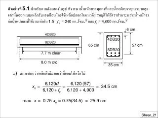
6 cm 4DB20 4DB20 8DB20 65 cm 57 cm 8DB20 7.7 m clear 8.0 m c/c 35 cm ตัวอย่างที่ 5.1 สำหรับคานดังแสดงในรูป พิจารณาน้ำหนักบรรทุกคงที่และน้ำหนักบรรทุกจรมากสุด จากนั้นออกแบบเหล็กรับแรงเฉือนโดยใช้เหล็กปลอกในแนวดิ่ง สมมุติให้อัตราส่วนระหว่างน้ำหนักจร ต่อน้ำหนักคงที่ใช้งานเท่ากับ 1.5f’c= 240 กก./ซม.2 และ fy= 4,000 กก./ซม.2 a) ตรวจสอบว่าเหล็กดึงมีมากกว่าที่ยอมให้หรือไม่ Shear_21
ecu=0.003 A’s=12.56 cm2 es max As=51.9 cm2 สำหรับ x= 25.9 ซม. max Cc = 0.85bb1(max x) = 0.85(0.24)(35)(0.85)(25.9) = 157.2ตัน Cs = A’sfy = 12.56(4.0) = 50.2ตัน Real As = 49.28 cm2 max T = max C = 157.2 + 50.2 = 207.4ตัน Shear_22
(b)หากำลังดัด Mn และน้ำหนักบรรทุกใช้งาน โดยสมมุติให้เหล็กอัดคราก 0.85(0.24)(35)(0.85x) + 12.56(4.0) = 49.28 (4.0) x = 24.2 ซ.ม. ยืนยันสมมุติฐานว่าเหล็กอัดคราก Cc = 0.85f‘cbb1x = 0.85(0.24)(35)(0.85)(24.2) = 146.9ตัน Cs = A’sfy = 12.56 (4.0) = 50.2ตัน T = Asfy = 49.28(4.0) = 197.1ตัน Mn = 146.9(46.7)/100 + 50.2(57-6)/100 = 94.2ตัน-เมตร Shear_23
wu = 10.6 ตัน/เมตร Max. shear at support: C of support L max. shear envelope 42.4 t SHD with DL+LL on entire span + 6.8 t Max. shear at midspan when half LL on span: - 6.8 t Midspan 42.4 t 8.0 m จากโจทย์กำหนดwL =1.5wDดังนั้น wu = 1.4wD +1.7(1.5wD) น้ำหนักบรรทุกคงที่ใช้งาน wD = 10.6/(1.4+2.55) = 2.7 ตัน/เมตร น้ำหนักจรใช้งานwL = 1.5(2.7) = 4.0ตัน/เมตร (c)ออกแบบเหล็กเสริมรับแรงเฉือน Shear_24
Face of support Critical section 36.0 t 42.4 t Required fVs d 72 cm 13.9 t fVc 6.8 t 0.5fVc C of support Midspan L Critical section from face of support d = 57 cm, support width = 30 cm Therefore compute Vu at 57+30/2 = 72 cm Shear_25
@ Critical section Required fVs = Vu- fVc = 36.0 - 13.9 = 22.1 ton Min fVs = 0.85(3.5)(35)(57)/1,000 = 5.9 ton Since 5.9 ton < Required fVs < 28.9 ton, max s = d/2 USE s = 13 cm from z = 0 to 57 cm from face of support From z = 57 cm, set fVn = Vu Shear_26
s (cm) fVs(ton) z (cm) 13.7 15 20 25 28.5 (d/2) 51.2 (NG) 22.1 (Max) 20.1 15.1 12.1 10.6 5.9 (Min) 0 to 57 79 135 169 186 238 6@13cm 4@15cm 2@20cm 8@25cm 30 cm 1 cm ตารางที่ 5.1 ความสัมพันธ์ระหว่างระยะห่างและกำลังสำหรับเหล็กปลอกในแนวดิ่ง Shear_27
Simplified method: More detailed equation: 7d/8 d/8 Replace Mu with Mm , where a/2 [SMA=0] A C Mu h/2 h d - a/2 Nu T Shear Strength of Members under Combined Bending and Axial Load Axial Compression where Nu = Factored axial compressive load Ag = Gross area of the concrete section Shear_28
Axial Tension 0.53 35.2 56.3 แรงอัด( Nu = + ), กก./ซม.2 แรงดึง( Nu = - ), กก./ซม.2 Shear_29
P P a a V = +P Shear Diagram + - V = -P M = Va Moment Diagram + Shear Span (a = M /V ) Distance a over which the shear is constant Shear_30
Variation in Shear Strength with a/d for rectangular beams Flexural moment strength Shear-compression strength Inclined cracking strength, Vc Failure moment = Va Shear-tension and shear-compression failures Deep beams Flexural failures Diagonal tension failures 0 1 2 3 4 5 6 7 a/d Shear_31
Mechanism: Use both horizontal and vertical may prevent cracks Compressive struts If unreinforced, large cracks may open at lower midspan. Deep Beams When shear span a = M /V to depth ratio < 2 Shear_32
Basic Shear Strength: fVnณ Vu where Vn = Vc + Vs Location for Computing Factored Shear: (a) Simply Supported Beams (Critical section located at distance z from face of support) - z = 0.15Lnณ d for uniform loading - z = 0.50a ณ d for concentrated loading (b) Continuous Beams Critical section located at face of support Shear_33
Simplified method: More detailed procedure: Upper limit: Upper limit of multiplier: when Mu/Vud = 0.4 Strength Vc - Simply Supported Beams Shear_34
Minimum Shear Reinforcement: min Av = 0.0015 bws where sฃ d / 5 ฃ 45 cm min Avh = 0.0025 bws2 where s2ฃ d / 3 ฃ 45 cm Strength Vs - Simply Supported Beams เมื่อ Av = พื้นที่เหล็กตั้งรับแรงเฉือน (ซม.2) Avh = พื้นที่เหล็กนอนรับแรงเฉือน (ซม.2) s = ระยะห่างเหล็กปลอกตั้ง (ซม.) s2 = ระยะห่างของเหล็กนอน (ซม.) Shear_35
Simplified method: More detailed procedure: Minimum Shear Reinforcement: min Av = 0.0015 bws where sฃ d / 5 ฃ 45 cm min Avh = 0.0025 bws2 where s2ฃ d / 3 ฃ 45 cm Strength Vc - Continuous Beams Strength Vs - Continuous Beams Shear_36
Limitation on Nominal Shear Strength Nominal stress vn = Vn / (f bwd) Shear_37
60 t 60 t 1.20 m 1.20 m 90 cm 4DB36 5 cm 5 cm 35@10 = 3.5 m 35 cm 40 cm 3.6 m 40 cm ตัวอย่างที่ 5.6 ออกแบบเหล็กรับแรงเฉือนสำหรับคานช่วงเดี่ยวรับน้ำหนักกระทำสองจุดของน้ำหนัก ใช้งานจร 60 ตันในแต่ละจุดในช่วงกว้างคาน 3.6 เมตร คานกว้าง 35 ซม. และความลึกประสิทธิผล d = 90 ซม. ใช้ f’c=280กก./ซม.2 และ fy= 4,000 กก./ซม.2 วิธีทำ (a) พิจารณาว่าเป็นคานลึกหรือไม่สำหรับคานนี้ Ln/d = 360/90 = 4 < 5ดังนั้นเป็นคานลึก Shear_38
ตัวคูณสำหรับคานลึกคือตัวคูณสำหรับคานลึกคือ (b) หน้าตัดวิกฤตสำหรับน้ำหนักกระทำเป็นจุด โดยใช้ช่วงคานเฉือน a = 1.20 ม. 0.50a = 0.5(1.20) = 0.60 ม < [d = 0.90 ม.] หน้าตัดวิกฤตอยู่ที่ 0.60 ม. จากผิวของจุดรองรับ (c) กำลังเฉือนของคานโดยไม่มีเหล็กรับแรงเฉือนที่หน้าตักวิกฤต น้ำหนักกระทำเป็นจุดประลัยคือ 1.7 LL = 1.7(60) = 102 ตัน ละเลยน้ำหนักคงที่ซึ่งน้อยเมื่อเทียบกับน้ำหนักกระทำเป็นจุด โดยใช้วิธีละเอียดที่หน้าตัดวิกฤต Shear_39
= 1.83[8.37 + 3.39] = 21.5 กก./ซม.2ควบคุม กำลังรับแรงเฉือนของคอนกรีต Vc = vcbwd = 21.5(35)(90)/1,000 = 67.8 ตัน (d) กำลังเฉือนที่หน้าตัดวิกฤต max Vn = 42.2(35)(90)/1,000 = 132.8ตัน > 120 ตันOK เนื่องจาก Vn ที่ต้องการ > Vc(120 > 67.8) ดังนั้นต้องการเหล็กเสริมรับแรงเฉือน Shear_40
(e) การเสริมเหล็กรับแรงเฉือน สำหรับ Ln/d = 4 : Vs = 120 – 67.8 = 52.2 ตัน b = 35 ซม. และ fy = 4,000 กก./ซม.2 min Av = 0.0015bws max s = d/5 =18 ซม. min Avh = 0.0025 bws max s2 = d/3 = 30 ซม. • ลองใช้ DB12 วางในแนวนอนในแต่ละด้านมีระยะห่างกัน 25 ซม. • minAvh= 0.0025(35)(25) = 2.2 ซม2 • ค่าที่เตรียมให้ Avh= 2(1.13) = 2.26 ซม2 > 2.2 ซม2 OK Shear_41
แทนค่า Avhลงในสมการ ดังนั้นใช้ DB12 เป็นเหล็กลูกตั้งทุกระยะ 10 ซม. ตลอดทั้งช่วงคาน สำหรับเหล็กลูกตั้ง DB12: Av = 2(1.13) = 2.26 ซม2 ต้องการ s= 2.26/0.222 = 10.2 ซม. < [d/5 = 18ซม.] OK Shear_42