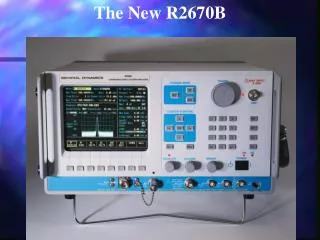

High-Speed Test System with Advanced Timing and Power Measurement Capabilities
E N D
Presentation Transcript
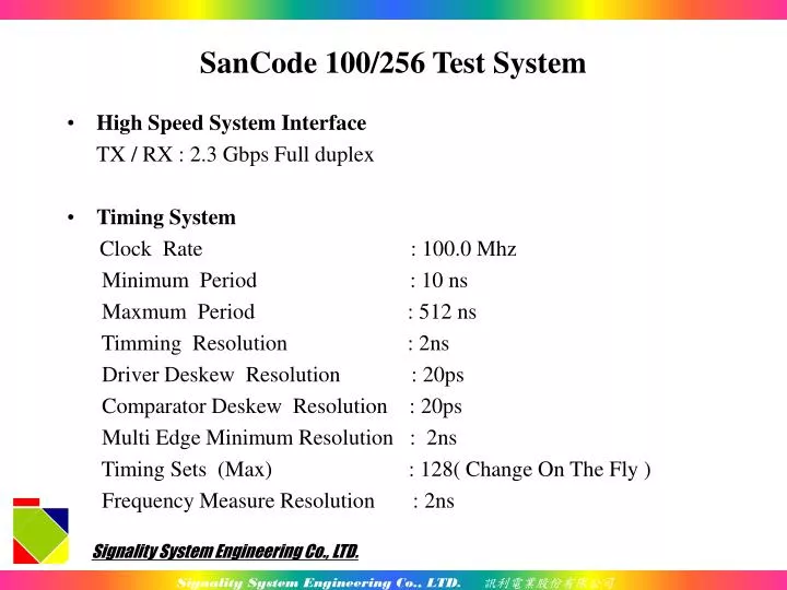
High Speed System Interface TX / RX : 2.3 Gbps Full duplex Timing System Clock Rate : 100.0 Mhz Minimum Period : 10 ns Maxmum Period : 512 ns Timming Resolution : 2ns Driver Deskew Resolution : 20ps Comparator Deskew Resolution : 20ps Multi Edge Minimum Resolution : 2ns Timing Sets (Max) : 128( Change On The Fly ) Frequency Measure Resolution : 2ns SanCode 100/256 Test System
Format RZ ,NRZ ,RTO ,SBC : Change On The Fly/Per Pin Driver Characters : 1,0,H,L,X,Z Comparator Characters : H \ . L A V Z Strobe Multi Window Strobe Resolution : 2ns Logical Analysis Resolution : 2ns,4ns,8ns,16ns Pattern Memory Main Pattern Memory : 128M/256M Per pin Capture Memory : 128M/256M Per pin Pattern Repeate Counter : 16 Bits Subroutine : Any Pattern Address Call Subroutine : 6 Level Loop Jump : 3 Level Loop Count : 16 Bits SanCode 100/256 Test System
DPS (Dut Power Supply) : 32Sets .8 DPS per Board .Voltage range : ±2V、±4V、±8V、-10V ~ +14V .Current range : ±2uA、±20uA、±200uA、±2mA、 ±20mA、±200mA、±1A .Clamp programmable : ±100% ~ ±10% per V/I range .Force and sense are independent and controllable .High Speed Measure : 4 Event .DPS Force Change On The Fly SanCode 100/256 Test System
Voltage Range Item/DescriptionMinMaxUnits ----Range 1 -2 +2 V Resolution 0.1 mV Accuracy -0.25% +0.25% FSR ----Range 2 -4 +4 V Resolution 0.2 mV Accuracy -0.25% +0.25% FSR ----Range 3 -8 +8 V Resolution 0.4 mV Accuracy -0.25% +0.25% FSR ----Range 4 -10 +13.5 V Resolution 0.5 mV Accuracy -0.25% +0.25% FSR SanCode 100/256 Test System
Current Range Item/DescriptionMinMaxUnits ----Range 1 -2 +2 uA Resolution 0.1 nA Accuracy -0.7% +0.7% FSR ----Range 2 -20 +20 uA Resolution 1 nA Accuracy -0.5% +0.5% FSR ----Range 3 -200 +200 uA Resolution 10 nA Accuracy -0.5% +0.5% FSR ----Range4 -2 +2 mA Resolution 100 nA Accuracy -0.5% +0.5% FSR SanCode 100/256 Test System
Current Range Item/DescriptionMinMaxUnits ----Range 5 -20 +20 mA Resolution 1 uA Accuracy -0.5% +0.5% FSR ----Range 6 -200 +200 mA Resolution 10 uA Accuracy -0. 25% +0.5% FSR ----Range 7 -1.0 +1.0 A Resolution 100 uA Accuracy -0.5% +0.5% FSR SanCode 100/256 Test System
Pin Electronics : Driver (VIH/VIL/VTT): ☛ Voltage range : -2V to +7V ☛ Resolution : 0.5mV ☛ Accuracy : ±25mV ☛ Rise/Fall time (p-p:10%~90%) : 1.6V/1.0ns ☛ Minimum Pulse Width : 3.0 ns (3V p-p) ☛ Output impedance : 50 Ω ☛ Static Current Driver : ±30mA Comparator : ☛ Voltage range : -2V to +7V ☛ Resolution : 0.5mV ☛ Accuracy : ±30mV ☛ Leakage : ±15nA SanCode 100/256 Test System
PPMU : ☛ Voltage range : -2V to +12V ☛ Current range : ±2uA、±8uA、±32uA、±128uA、±512uA、 ±2mA、±8mA、±32mA ☛ Clamp Voltage programmable Voltage Item/DescriptionMinMaxUnits ----Range -2 12 V Resolution 0.5 mV Accuracy -25 +25 mV SanCode 100/256 Test System
Current Item/DescriptionMinMaxUnits ----Range 1 -2 +2 uA Resolution 0.3 nA Accuracy -30 +30 nA ----Range 2 -8 +8 uA Resolution 1.2 nA Accuracy -90 +90 nA ----Range 3 -32 +32 uA Resolution 4.8 nA Accuracy -320 +320 nA ----Range 4 -128 +128 uA Resolution 19.2 nA Accuracy -1.25 +1.25 uA SanCode 100/256 Test System
Current Item/DescriptionMinMaxUnits ----Range 5 -512 +512 uA Resolution 76.8 nA Accuracy -5 +5 uA ----Range 6 -2 +2 mA Resolution 307.2 nA Accuracy -20 +20 uA ----Range 7 -8 +8 mA Resolution 1.23 uA Accuracy -80 +80 uA ----Range 8 -32 +32 mA Resolution 4.92 uA Accuracy -320 +320 uA Handler / Probe interface : • IEEE-488 (GPIB) • Probe / Handler (TTL parallel) SanCode 100/256 Test System
Power Consumption Static Dynamic +5V 40.6A( 203.0W) 40.9A -3V 18.4A( 55.2W) 18.4A +18V 6.5A( 117.0W) 6.7A -12V 16.2A( 194.4W) 16.2A Total 569.2W SanCode 100/256 Test System
There are three components to construct a drive waveform for Sancode system -TIMING_SET, LEVEL_SET & Pattern. Waveform format is implied in TIMING_SET. Four implied drive & IO waveform format:NRZ、RZ、RTO & SBC. Only one implied waveform format in one period, Sancode can repeat the selected waveform format in the same cycle. Minimum pulse width 4ns, i.e. maximum clock rate 125MHz. Timing skew per pin include drive, IO & strobe. Timing resolution 2ns. Skew resolution 20ps. Multi-window strobe. Waveform Programming Description
Waveform Programming Description (cont.) 0 1 1 0 0 PAT TG NRZ RZ RTO SBC
Waveform Programming Description (cont.) Repeat the selected waveform format in the same cycle
Waveform Programming Description (cont.) Timing delay
Waveform Programming Description (cont.) Multi-window Strobe