Download
1 / 15
150 likes | 248 Views
Learn how to transition from truth tables to equations in combinational logic circuits. Study the application of AND and OR gates to detect specific input patterns. Optimize circuit design by minimizing terms and understanding the logic adjacency theorem.

E N D
EEE515J1Combinational Logic: Truth tables to equations Ian McCrum Room 5D03B Tel: 90 366364 voice mail on 6th ring Email: IJ.McCrum@Ulster.ac.uk Web site: http://www.eej.ulst.ac.uk www.eej.ulst.ac.uk/~ian
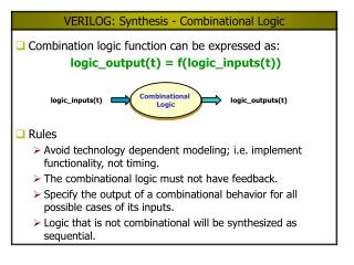
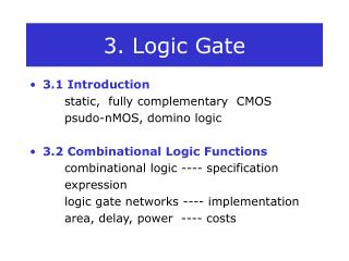
Two example circuits www.eej.ulst.ac.uk/~ian
To analyse the bottom circuit • Create a table with columns for the 8 possible input patterns. • There are 3 inputs so there are 2^3=8 unique input patterns • Add columns and labels for intermediate signals as well as the output www.eej.ulst.ac.uk/~ian
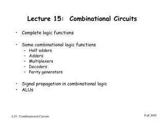
To come up with a circuit from a truth table, concentrate on each output at a’1’ that is needed We need to detect four particular input patterns, {010,011,110,111} This could be done by using a three input AND gate to detect each ‘1’ and then ORing each of the “on-term” detectors. www.eej.ulst.ac.uk/~ian
“On-term” detectors also called “Product Term detectors I.E go high when the input is /AB/C This type of circuit is called AND-OR And directly generates the SUM of PRODUCTS (SOP) form Y=/ABC + /ABC + AB/C + ABC e.g. to detect the product term {110} (sometimes called m6) we use an invertor on C, so the AND gate will go high when the input is AB/C www.eej.ulst.ac.uk/~ian
A B C AND OR i.e. Generate a ‘1’ when inputs are 010 or 011. Also generate a ‘1’ when the inputs are 110 or 111. but for an input pattern of 010 or 011 you only need to detect 01 on the A and B inputs. (/AB) Likewise detect 11 on the A or B inputs, C can be either a ‘0’ or a ‘1’ – it doesn’t matter. Hence use the term AB. Now Y=/AB+AB ; again A can be ‘0’ or ‘1’ so the answer is just B Note again in the truth table, the bold terms are when we want to o/p to be a ‘1’. www.eej.ulst.ac.uk/~ian
With practice you can spot these minimisations by inspection. They are examples of the “logic adjacency theorem” – if two product terms are absolutely identical except they differ in having one variable in a normal form in one term and in the complementary form in the other term then you can remove that term. Taking the first pair of ones… /A B /C + /A B C = /A B www.eej.ulst.ac.uk/~ian
What you should know • How to write down a SOP equation from a truthtable • Save ink if possible and be quick (try and apply the adjacency theorem by inspection) Don’t worry if you don’t/can’t • If you really need to minimise – use a computer! See the package McBoole or let Quartus do it for you. www.eej.ulst.ac.uk/~ian
Points so far • A product term or minterm or “on-term” generates a ‘1’ output in a truth table • A canonical product term contains every variable • The “Sum of Product form or AND-OR circuit is a useful way of generating an o/p • Two product terms can be combined – and a variable is removed, by using the adjacency theorem • We can cost circuits – according to a “Cost model” www.eej.ulst.ac.uk/~ian
Cost models • What costs? • Silicon area • Gate count • Power consumption • Speed • Number of soldered joints • Number of packages • Number of unusual packages • Stores inventory • Etc…!!! www.eej.ulst.ac.uk/~ian
“McCrum’s Cost Model” • The simplest I could come up with and still allows you to show you have thought about costing. • One penny per gate input, with free invertors! • Later on we will add 6p per D-type flop-flop and 9p for any other flip-flop type. www.eej.ulst.ac.uk/~ian
Example 3p 2p+2p+3p+3p = 10p A canonical solution will cost 3p+3p+3p+3p + 4p = 16p Since the truth table had 4 on-terms in it – 4 product term detectors each of which was a 3 i/p AND gate. www.eej.ulst.ac.uk/~ian
Tutorials (verify by quartus!) ABCD P Q R S This is taken from the file super13.doc. It is 4 separate circuits – one for P, one for Q, one for R and one for the S output. There are 4 inputs A,B,C and D. Generate the schematics and simulate to prove the truthtable/schematic is correct. [Tut L2_1, L2_2, L2_3 and L2_4] We could also specify this problem by numbering the input patterns, m0 to m15 Thus P = f(ABCD) = ∑(m7-m12, m14) Some software will allow the use of don’t care terms, using a ‘d’ or ‘x’ term. See the file McBoole.txt in the files section of the website for an example. www.eej.ulst.ac.uk/~ian
More costings [Tutorials] ABCD P Q R S Each product term will require a 4 input AND gate, ignoring m13 we need 15 such gates or 60p P needs a 7 i/p OR Q needs a 7 i/p OR R needs a 8 i/p OR S needs a 7 i/p OR Total cost = 89p (cost of P is 35p) This solution costs 4p+3p+3p+3p for AND gates and 4p for the output gate for P (cost of P is 13p) TUT L2_5; what is a more minimal cost of Q,R and S? www.eej.ulst.ac.uk/~ian
Conclusion • A product term or minterm or “on-term” generates a ‘1’ output in a truth table • A canonical product term contains every variable • The “Sum of Product form or AND-OR circuit is a useful way of generating an o/p • Two product terms can be combined – and a variable is removed, by using the adjacency theorem • We can cost circuits – according to a “Cost model” • Be able to move from truth tables to AND-OR equations and circuits • Be able to do a little minimisation be inspection • Be able to “cost” a circuit • You now have 5 tutorials to try! [Tut L2_1 to L2_5] www.eej.ulst.ac.uk/~ian