Download
1 / 51
650 likes | 1.22k Views
Overview of Combined Cycle Turbine Technology. Matthew esper , BSME ’06 – u of m. MECHANICAL ENGINEER ENERGY. AGENDA. Who Is Black & Veatch? Overview of Traditional Thermal Cycles Overview of Combined Cycles Major Equipment of Combined Cycles Design Options for Combined Cycles

E N D
Overview of Combined Cycle Turbine Technology Matthew esper, BSME ’06 – uofm MECHANICAL ENGINEER ENERGY
AGENDA • Who Is Black & Veatch? • Overview of Traditional Thermal Cycles • Overview of Combined Cycles • Major Equipment of Combined Cycles • Design Options for Combined Cycles • Air Quality Control for Combined Cycles • Review of Latest CTG in CC Technology Options • New Hire Responsibilities • Questions AGENDA 2
WE’RE BUILDING A WORLD OF DIFFERENCE. TOGETHER. Who is black & veatch? Founded in 1915 Global workforce of more than 10,000 Employee-owned corporation $3.6 billion in annual revenues in 2013 More than 110 offices worldwide Completed projects in more than 100 countries Black & Veatch conducts 7,000+ active projects globally at any one time
Solving the world’s complex challenges in each of our markets Energy Water Telecommunications Indonesia Hong Kong SAR California, USA Using teamwork and collaboration we provide sustainable and reliable solutions WHO IS BLACK & VEATCH? Security Management Consulting Environmental Armenia Oklahoma, USA Scotland, UK
Black & Veatch provides Construction services to the energy, water, telecommunications and FEDERAL MARKETS Who is black & veatch? Black & Veatch Construction, Inc. (BVCI) for union construction Overland Contracting Inc. (OCI) for open shop construction Black & Veatch International (BVI) for work outside the U.S. We have extensive construction experience on projects of complex size and scope throughout the world
THE RESULT IS A POSITION OF INDUSTRY LEADERSHIP ENR 1st – Top 20 in Telecommunications 1st – Top 25 in Fossil Fuel 3rd – Top 20 in Power 3rd – Top 20 in Transmission Lines and Aqueducts 4th – Top 25 in Transmission and Distribution Plants 4th – Top 20 Contractors in Telecom 5th– Top 10 in Hydroplants 5th– Top 20 in Nuclear Plants 5th– Top 15 in Dams and Reservoirs 6th – Top 25 in Wastewater Treatment Plants 6th– Top 25 in Sanitary and Storm Sewers 6th– Top 20 in Water 8th – Top 20 in Sewerage and Solid Waste 9th – Top 20 Contractors in Power 10th– Top 20 in Water Treatment, Desalination Plants 11th – Top 50 Contractors Working Abroad 12th– Top 25 in Refineries and Petrochemical Plants 16th– Top 500 Design Firms Engineering News-Record Who is black & veatch? CENTURION RESEARCH SOLUTIONS 2nd– Top 100 Federal Contractors Architectural & Engineering Services
BLACK & VEATCH HAS REGIONAL OFFICES THROUGHOUT THE UNITED STATES Arizona California Colorado Delaware District of Columbia Florida Georgia Illinois Indiana Kansas Kentucky Louisiana Maryland Massachusetts Michigan Minnesota Missouri Nebraska Nevada New Jersey New York North Carolina Ohio Oregon Pennsylvania South Carolina Texas Virginia Washington Who is black & veatch? Project offices are not included.
OUR GLOBAL Presence allows us to APPLY GLOBAL EXPERTISE LOCALLY Who is black & veatch? Afghanistan Armenia Australia Azerbaijan Bahrain Canada Chile China Czech Republic Georgia Hong Kong India Indonesia Kuwait Kazakhstan Malaysia Mexico Netherlands Oman Palestine Philippines Puerto Rico Russia Saudi Arabia Singapore South Africa Taiwan Thailand Turkey Ukraine United Arab Emirates (UAE) United Kingdom United States Vietnam
Michigan Business Began in 1980 Ann Arbor Office Opened in 1988 260 Skilled Personnel Coal Plants Gas Turbines Combined Cycle Gasification / IGCC Renewables AQCS Energy Services Power Delivery Substations ANN ARBOR Office Overview Who is black & veatch? 10
WE UNDERSTAND THE ENTIRE LIFE CYCLE OF A POWER PLANT OutageManagementPlanning ProjectCompletion DetailedEngineering Preliminary Schedules Select MajorEquipment Detailed CostEstimates FeasibilityStudy Construction /ConstructionManagement SystemsAnalysis Licensing /Permitting SoilsTesting ProjectSchedule Optimization Who is black & veatch? ProjectPlanning &Controls MarketAssessment Maintenance& OutageServices PermittingSupport ArrangementDrawings Monitoring /Diagnostics Monte CarloAnalysis Startup Operator Training PreliminaryCostEstimates PlantConfigurationStudy SystemDefinitions CommercialContractingStrategies Retirement /Decommissioning Procurement Feasibility / Initial Engineering Conceptual / Definition Engineering Project Execution Operations
Grayling Gateway B&V ENERGY – ANN ARBOR PROJECTS Dallman • Coal Plants • Gasification / IGCC • Biomass • Carbon Capture • Pre-combustion • Post-combustion • Gas Turbines • Combined Cycle • Traditional HRSG • Solar Thermal Hybrid • Nuclear • AQCS • Wind Who is black & veatch? Mesquite Black & Veatch has been involved in more megawatts of power generation than any other company: 121,000+ MW worldwide
TYPES OF POWER PLANTS • Simple Cycle Combustion Turbine (Brayton Cycle) • Coal Fired Thermal Plant (Rankine Cycle) • Combined Cycle Plant (Brayton/Rankine) • Cogeneration Plant OVERVIEW Of Combined Cycle TURBINE Technology 13
Traditional Coal Fired Power Plant (Low Sulfur Coal Basis) OVERVIEW Of Combined Cycle TURBINE Technology 14
CWLP Dallman Unit 4 (Commercial Operation Fall 2009) Unit 4 – 200 MW Net with Pulverized Coal Boiler OVERVIEW Of Combined Cycle TURBINE Technology 15
Simplified Combined Cycle Power PlantCombination of Brayton (Gas) and Rankine (Steam) Cycles OVERVIEW Of Combined Cycle TURBINE Technology 16
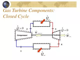
CYCLE DIAGRAMS OVERVIEW Of Combined Cycle TURBINE Technology 17
Mesquite Generating Station (Commercial Op. 2003) 1250 MW Net with Natural Gas Fired Combustion Turbines and Duct Burners OVERVIEW Of Combined Cycle TURBINE Technology 18
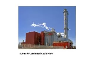
Gateway Generating Station (Commercial Op. 2009) 600 MW Net with Natural Gas Fired Combustion Turbines, Duct Burners, Chillers OVERVIEW Of Combined Cycle TURBINE Technology 19
Major Equipment of Combined Cycles Combustion Turbines Heat Recovery Steam Generators OVERVIEW Of Combined Cycle TURBINE Technology Steam Turbines 20
Combustion Turbines • Aeroderivatives are generally utilized for simple cycle peaking due to their high simple cycle efficiency and low exhaust gas temperature • New combined cycles generally utilize F, G, H, or J Class heavy duty frame type CTGs • F, G, H and J Class CTGs have axial exhaust and cold end drives • F Class utilize compressor air for cooling hot components (ie, turbine blades and transition pieces) • G and J Class machines (MHI) utilize steam cooling (exception is M501GAC) • Current H Class machines (GE and Siemens) do not utilize steam cooling, air cooled OVERVIEW Of Combined Cycle TURBINE Technology 21
Combustion Turbines – Turbine Inlet Temp (Tfire) OVERVIEW Of Combined Cycle TURBINE Technology 22
Combustion Turbines TURBINE EXHAUST COMBUSTION CANS OVERVIEW Of Combined Cycle TURBINE Technology TURBINE SECTION COMPRESSOR SECTION 23
HISTORICAL PrimE Movers F Class CF E Class • Primary Suppliers • ABB • GE • Westinghouse • Siemens V-Class 1980’s to 2000’s, we saw 4 primary classes of engines serving the U.S. market OVERVIEW Of Combined Cycle TURBINE Technology AERO Early Frame 150 100 200 50 MW
Today’s CT Choices GE 7HA.02 Series Siemens H Siemens F5 MPS J GE 7HA.01 Alstom LMS 100 LM6000 MPS G CF OVERVIEW Of Combined Cycle TURBINE Technology OEMS have filled in the MW gaps, increased MW and improved efficiency GE 7F.05 300 200 100 150 250 MW
9/30/2014 Today’s CT Product Line (>850 mmbtu/hr) NSPS = 1000 lb/MWh for Larger CTs OVERVIEW Of Combined Cycle TURBINE Technology
Today’s CT Product Line Combined cycle efficiency > 61% OVERVIEW Of Combined Cycle TURBINE Technology
HRSGs are large air-to-water & steam heat exchangers Tube bundles include superheater, reheater, evaporator, and economizer sections Heat Recovery Steam Generators OVERVIEW Of Combined Cycle TURBINE Technology 28
Heat Recovery Steam Generator (HRSG) Stack Steam Drum Outlet Duct Internal Insulation and Lagging Inlet Ducts OVERVIEW Of Combined Cycle TURBINE Technology Expansion Joint Economizer Section Downcomer Evaporator Section Internal Structural Steel Superheater Section Expansion Joint 29
Heat Recovery Steam Generator Erection OVERVIEW Of Combined Cycle TURBINE Technology 30
Heat Recovery Steam Generator Erection OVERVIEW Of Combined Cycle TURBINE Technology 31
Heat Recovery Steam Generator Erection Heat Transfer Module (Tube Bundle) Placement Each bundle may have 12 or more tube rows OVERVIEW Of Combined Cycle TURBINE Technology Tube to Header Welds 32
Startup (warm up) time requirements vary and play significant factor in combined cycle startup times The steam turbine can be purchased with the combustion turbine or can be purchased separately Possible suppliers include: General Electric, Siemens, Toshiba, Mitsubishi, Alstom, Hitachi Steam Turbines OVERVIEW Of Combined Cycle TURBINE Technology 33
HRSG Duct Burners for Raising STG Power Inlet Air Cooling (Evaporative or Chillers) Fuel Gas Heating Startup Time Considerations Design Options for Combined Cycles OVERVIEW Of Combined Cycle TURBINE Technology 34
Duct firing raises steam turbine power output Utilized when grid electrical demand is high Duct burner sizing depends on the Customers requirements Heavy Duct Firing = Duct Burner Exit Temperature 1500 to 1600 F Heavier duct firing results in a greater efficiency penalty HRSG Duct Burners OVERVIEW Of Combined Cycle TURBINE Technology 35
Typical Combined Cycle Design – Duct Burners On Design Features: 2 CTGs x 1 STG Combustion Turbines GE 7FA.04* 3 Pressure Reheat Includes Duct Burners for 43 MW or 22% Output Boost for Steam Turbine Fired Condition Light Duct Firing OVERVIEW Of Combined Cycle TURBINE Technology 36
Typical Combined Cycle Design – Duct Burners Off Design Features: 2 CTGs x 1 STG Combustion Turbines GE 7FA.04* 3 Pressure Reheat Includes Duct Burners for 43 MW or 22% Output Boost for Steam Turbine Unfired Condition OVERVIEW Of Combined Cycle TURBINE Technology 37
Other Duct Fired 2x1 7FA Design Examples OVERVIEW Of Combined Cycle TURBINE Technology • Note Ambient Temperature and Heat Rejection Differences • Note Change in STG Throttle Pressure from Unfired to Fired Condition • Sliding STG Inlet Pressure • Three Separate Project Examples • Same CTG, Different Cycle Designs • Light Firing Increased STG Output 22% • Heavy Firing Increased STG Output 75% 38
Combustion turbine inlet air cooling raises CTG power output Evaporative coolers are relatively inexpensive, but consume water Incorporated into the inlet air filter housing by the CTG OEM Evaporative coolers are most effective in arid climates, but are frequently included in plant designs for all types of climates Inlet Air Cooling (Evaporative Type) OVERVIEW Of Combined Cycle TURBINE Technology 39
Chillers are expensive, but yield greater CTG power output increase Typically sized to reduce CTG inlet air temperature to 50 F from some specific ambient condition Typically water is a byproduct, condensed from the ambient air, and can be utilized elsewhere within the power plant The chilling heat transfer coil is integrated into the inlet air filter housing by the CTG OEM Chilling system designs vary, particularly the fluid passing through the coil that chills the ambient air (typically chilled water) Refrigerant types: anhydrous ammonia, R-123, etc Unlike evaporative coolers, inlet air chillers yield an efficiency penalty Inlet Air Cooling (Chiller Type) OVERVIEW Of Combined Cycle TURBINE Technology 40
Inlet Air Chilled 2x1 7FA Design Example OVERVIEW Of Combined Cycle TURBINE Technology • Chiller primarily increases CTG power • STG power is increased if it is not already at maximum output due to duct firing • If STG was already fired to the maximum, duct firing is reduced • STG power increase is due to increased CTG exhaust energy to the HRSG • Chiller operation yields slight efficiency penalty 41
Fuel gas heating increases the efficiency of the combined cycle Low grade heat from the HRSG is used to pre-heat the fuel gas which improves combustion turbine heat rate The heated fuel gas temperature will depend on the CTG OEM Values between 280 F and 365 F are common The temperature must be controlled to a stable set point or the CTG will run back or trip Typically feed water from either the LP drum (280 F) or the IP economizer exit (365 F) is utilized to heat the fuel gas Fuel Gas Heating OVERVIEW Of Combined Cycle TURBINE Technology 42
Startup emissions are often limited by air permits Agencies understand startup emissions can be minimized Faster startups consume less fuel and thus save the Owner money Fast startups allow the operator to hit higher outputs faster, increasing revenue for merchant generators Combined cycles will increasingly be required to start and/or change loads quickly as wind turbine farm output and/or solar energy output to the grid varies Startup Time Considerations Startup times are an increasingly important consideration for combined cycles due to the following: OVERVIEW Of Combined Cycle TURBINE Technology 43
Changing system dynamics Impact of wind generation on power system load • Wind is intermittent and is a major contributor during low load hours, but only minimal during peak load hours • Wind generation requires a generation mix with more operational flexibility to serve the net load Addition of wind generation: Net Load Duration Curve becomes more steep Wind generation has small (but not zero) impact on peak load Hydro Gas GT OVERVIEW Of Combined Cycle TURBINE Technology Peaking Generation Peaking Generation System Load Mid-Merit Generation Gas CCGT Mid-Merit Generation Base Load Generation Base Load Generation Hours of Operation / Year Wind generation has major impact on low and minimum load conditions 44 System Load without wind Clean Coal Net System Load with wind
New large combined cycles in the United States typically include the following air quality control equipment and features: Dry Low NOx burners for the CTG Selective Catalytic Reduction (SCR) system in the HRSG for NOx reduction Ammonia injection for the HRSGs SCR Carbon Monoxide (CO) catalyst in the HRSG for CO and VOC reduction Air Quality Control for Combined Cycles OVERVIEW Of Combined Cycle TURBINE Technology 45
How Does an Entry-Level Mechanical EngineerGet involved? System Engineer • Development of system P&ID’s • Service/Potable Water • Station Air • Compressed Gases • Wastewater Collection • System and equipment sizing calculations • Centrifugal/Vertical Sump Pumps • Air Compressors/Dryers • System Piping • Development of technical specifications for equipment • Pumps/Compressors • Valves/Miscellaneous Piping Devices Pipe Stress Engineer • Modeling of piping systems • Pipe materials, temperatures & pressures • Model supports • Thermal growth • Wind & seismic activity • Verify design meets equipment and code allowables • Pipe support detail drawings • Anchors, rod hangers, springs, struts & shock absorbers OVERVIEW Of Combined Cycle TURBINE Technology 46
What is a P&ID? OVERVIEW Of Combined Cycle TURBINE Technology 47
What is a Piping Isometric? OVERVIEW Of Combined Cycle TURBINE Technology 48
Pipe Stress analysis OVERVIEW Of Combined Cycle TURBINE Technology 49
Career Relevant Coursework System Engineer • Major Required: • Thermodynamics • Fluid Mechanics • Heat Transfer • Electives • Intro to Combustion • Energy Conversion • Computer Assisted Design of Thermal Systems • Design of Alternative Energy Systems Pipe Stress Engineer • Major Required: • Materials Science & Engineering • Statics • Electives • Intermediate Mechanics of Deformable Solids • Computer Aided Design of Structures • Finite Element Analysis OVERVIEW Of Combined Cycle TURBINE Technology 50