Download

1 / 13
130 likes | 301 Views
Accurate Model-to-Hardware Simulation Methodology for Designing Critical Path Monitors over a Wide Voltage Range. Alan J. Drake 1 , Xiaobin Yuan 2 , Pawel Owczarczyk 2 , Marshall Tiner 2. 1 IBM Research 2 IBM System and Technology Group. Introduction.

E N D
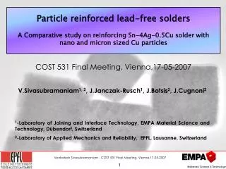
Accurate Model-to-Hardware Simulation Methodology for Designing Critical Path Monitors over a Wide Voltage Range Alan J. Drake1, Xiaobin Yuan2, Pawel Owczarczyk2, Marshall Tiner2 1IBM Research2IBM System and Technology Group
Introduction • DVFS control systems need real-timing timing margin information • Critical path monitors must provide accurate timing measurements across a wide voltage and frequency range • Accurate static timing to check for early and late mode failures insufficient • High accuracy simulations of extracted netlists are costly • Developed a method to design a CPM that meets operating ranges while minimizing simulation time.
Critical Path Monitor Overview Calibration delay Multiple synthesis paths to mimiccritical paths
Calibration Delay • Coarse delay block equal to sum of fine delay blocks • Muxes combine delay into continuous range
Tuning Methodology • Hierarchical simulation • Fine delay lines only • Synthesis paths without control • Multiple runs required • 4 paths • 2 guardband frequencies • 3 operating points: powersave, nominal, and turbo • multiple process corners Design Data Extraction Simulation Compare to target Update design n = y
Extraction and Simulation • Hierarchical • Control: 10724 transistors • Custom synthesis block: 5257 transistors • Extraction • Full coupling for power and noise analysis • Reduced coupling for timing • Simulation • Spice • Slow (6hrs, 34mins) but flexible for all possible corners • Accuracy dependent on extraction • Static timing • Fast (50 minutes) • Very accurate at 2 points: early and late mode timing
HW1: Static Timing Only CPM0 Path1 Low-Vt • Calibration delay at multiple voltage and temperature points • 4 chips tested • 4 paths per CPM, 5 CPMs per core, up to 8 cores per chip • 13 delay step spread • Heavy, steady-state workload • Dark blue: 0.9V, 50C • Magenta: 1.1V, 60C • Cyan: 1.3V, 60C • Yellow: 1.3V, 80C CPM0 Path2 Low-Vt Wire Occurrence CPM0 Path3 Mid-Vt CPM0 Path4 High-Vt Target delay More delay Less delay
HW2: Static Timing Only After Adjusting for Path Offsets • Calibration delay at multiple voltages • More than 20 parts tested • High-Vtdistribution shifts right and lines up with Low-Vt inverter • Low-Vt distributions shift left • Mid-Vt distribution shifted right
HW2: Bit-to-bit Calibration Delay Spreads All Operating Points Interpolating Delay Inverter Coarse Delay
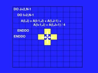
Simulated Range with More Detailed Extraction:Full Frequency Range
Simulated Tuning and Sampling Step Sizes Edge Detector • Normalized to nominal cycle time Tuning delay • Normalized to nominal cycle time • Includes fine delay and interface between course step and fine step
Conclusion Single tool simulation insufficient to guarantee accuracy required over process, corners, and guardband Hierarchy needed to keep simulation times reasonable Mix of extraction and simulation environments essential Accurate capacitive coupling extractions necessary to accurately predict small frequency differences in delay elements