Download
1 / 39
390 likes | 577 Views
Applying Control Theory to the Caches of Multiprocessors. Kai Ma. Department of EECS University of Tennessee, Knoxville. Applying Control Theory to the Caches of Multiprocessors. Shared L2 cache is one of the most important on-chip shared resource. Largest area and leakage power consumer

E N D
Applying Control Theory to the Caches of Multiprocessors Kai Ma Department of EECSUniversity of Tennessee, Knoxville
Applying Control Theory to the Caches of Multiprocessors • Shared L2 cache is one of the most important on-chip shared resource. • Largest area and leakage power consumer • One of the dominant players in terms of performance • Two Papers: • Relative Cache Latency Control for Performance Differentiations in Power-Constrained Chip Multiprocessors • SHARP Control: Controlled Shared Cache Management in Chip Multiprocessors
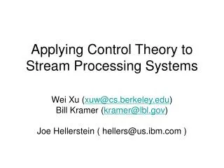
Relative Cache Latency Control for Performance Differentiations in Power-Constrained Chip Multiprocessors Xiaorui Wang, Kai Ma, Yefu Wang Department of EECSUniversity of Tennessee, Knoxville
Background NUCA (Non Uniform Cache Architecture) Key idea: Different cache banks have different access latencies. 13
Introduction • The power of the cache part needs to be constrained. • With controlled power, the performance of the caches also need to be guaranteed. • Why control relative latency (the ratio between the average cache access latencies of two threads)? • 1. Accelerate critical threads 2. Reduce priority inversion
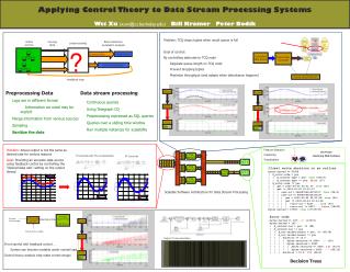
System Design Latency Monitor Latency Monitor Thread 1 on core 1 Thread 0 on core 0 Cache bank of Thread 0 Relative Latency Controller Cache bank of Thread 1 Cache Resizing and Partitioning Modulator Relative Latency Controller Cache bank of Thread 2 Cache bank of Thread 3 Relative Latency Controller Inactive cache bank Power Monitor Power Controller Relative Latency Control Loop Power Control Loop Shared L2 Cache Thread 3 on core 3 Thread 2 on core 2 Latency Monitor Latency Monitor
Relative Latency Controller (RLC) • Workload variation • Total cache size variation Error: 0.3 Increase 0.2 Relative latency set point RLC Shared L2 caches RL New cache ratio 1.5 1.5 1.2 • PI (Proportional-Integral) controller • System modeling • Controller design • Control analysis
Relative Latency Model • is the relative latency between and core • is the cache size ratio between and core • RL model • System identification • Model orders • Parameters Model Orders and Error
Controller Design • PID controller • Proportional • Integral • Design: Root Locus Relative Latency set point Shared L2 caches Relative latency New cache ratio Error
Control Analysis • Derive the transfer function of the controller • Derive the transfer function of the system with system model variations • Derive the transfer function of the close-loop system and compute the poles Stability range: The control period of the power control loop is selected to be longer than the settling time of the relative latency control loop.
Power Controller • is the total cache size in the power control period. • is the cache power in the power control period. • are the parameters depended on applications • System Model • Leakage power is proportional to the cache size. • Leakage power counts for the largest portion of cache power. • PI Controller • Controller analysis: and
Simulation • Simulator • Simplescalar with NUCA cache (Alpha 21264 like core) • Power reading • Dynamic part: Wattch (with CACTI) • Leakage part: Hotleakage • Workload • Selected workloads from SPEC2000 • Actuator • Cache bank resizing and partitioning 3 3 3 3 1 1 1 1 2 2 2 2 6 6 6 6 7 7 7 7 4 4 4 4 5 5 5 5 10 10 10 10 11 11 11 11 8 8 8 8 9 9 9 9 14 14 14 14 15 15 15 15 12 12 12 12 13 13 13 13 16 16 16 16
Single Control Evaluation RLC set point change Power controller set point change Workload switch Total cache bank count change Switch workloads here
Coordination Cache access latencies and IPC values of the four threads on the four cores of the CMP. Cache access latencies and IPC values of the two threads on Core 0 and Core 1 for different benchmarks.
Conclusions • Relative Cache Latency Control for Performance Differentiations in Power-Constrained Chip Multiprocessors • Simultaneously control power and relative latency • Achieve desired performance differentiations • Theoretically analyze the single loop control and coordinated system stability
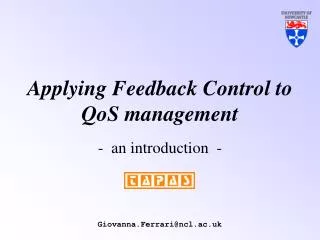
SHARP Control: Controlled Shared Cache Management in Chip Multiprocessors Shekhar Srikantaiah, Mahmut Kandemir, *Qian Wang Department of CSE *Department of MNE The Pennsylvania State University
Introduction • Lack of control over shared on-chip resource • Faded performance isolation • Lack of Quality of Service (QoS) guarantee • It is challenging to achieve high utilization meanwhile guaranteeing the QoS. • Static/dynamic resource reservations may lead to low resource utilization. • Existing heuristics adjustment cannot provide theoretical guarantee like “settling time” or “stability range”.
Contribution • Two-layer control theory based SHARP (SHAred Resource Partitioning) architecture • Propose an empirical model • Design a customized application controller (Reinforced Oscillation Resistant controller) • Study two policies can be used in SHARP • SD (Service Differentiation) • FSI (Fair Speedup Improvement)
Why not PID? • Disadvantages of PID (Proportional-Integral-Derivative) controller • Painstaking to tune the parameters • Hard to be integrated with hierarchical architecture • Sensitive to model variation during run time • Static parameters • Generic controller (not problem-specific) • Linear model based controller
Pre-Actuation Negotiator (PAN) • Map an overly demanded cache partition to a feasible partition • Policies: • SD (Service Differentiation ) • FSI (Fair Speedup Improvement )
SHARP Controller • Increase IPC set points when cache ways are under utilized • FSI & SD policies • The proof of guaranteed optimal utilization
Experimental Setup • Simulator : Simics (Full system simulator) • Operating System: Solaris 10 • Configuration (2, 8 cores) • Workload: • 6 mixes of applications selected from SPEC2000
Evaluation (Application Controller) Long run results of PID controller and ROR controller
Evaluation (FSI) SHARP vs Baselines
Evaluation (SD) Adaptation of IPC with the SD policy using the ROR controllers.
Sensitivity & Scalability Sensitivity analysis for different reference points Scalability (8 cores)
Conclusion • SHARP Control: Controlled Shared Cache Management in Chip Multiprocessor • Propose and design the SHARP control architecture for shared L2 caches • Validate SHARP with different management policies (FSI or SD) • Achieve desired FS and SD specifications
Critiques (1) How to decide the relative latency set point? For accelerating critical thread purpose, the parallel workloads may be more applicable.
Critiques (2) • No stability proof • Insufficient description about how to update the parameters for the application controllers
Q & A • Thank you
Guaranteed Optimal Utilization Proof • are time varying coefficient depended on applications