STORED PROGRAM CONCEPT
STORED PROGRAM CONCEPT. RESOURCE GUIDE. Understand how the von Neumann architecture is constructed. Understand how the von Neumann architecture works. Understand how to program in basic assembly languag e. The Stored Program Concept.

STORED PROGRAM CONCEPT
E N D
Presentation Transcript
STORED PROGRAM CONCEPT RESOURCE GUIDE
Understand how the von Neumann architecture is constructed. Understand how the von Neumann architecture works. Understand how to program in basic assembly language.
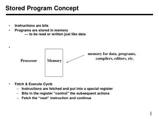
The Stored Program Concept Von Neumann’s proposal was to store the program instructions right along with the data The stored program concept was proposed about fifty years ago; to this day, it is the fundamental architecture that fuels computers. Think about how amazing that is, given the short shelf life of computer products and technologies…
The Stored Program Concept and its Implications • The Stored Program concept had several technical process: • Four key sub-components operate together to make the stored program concept work • The process that moves information through the sub-components is called the “fetch execute” cycle • Unless otherwise indicated, program instructions are executed in sequential order
Control Unit The last of the four subcomponents is the Control Unit. The control unit is the part that drives the fetch and execute cycle. We mentioned in memory, a cell address is loaded into the MAR – it is the control unit that figures out which address is loaded, and what operation is to be performed with the data moved to the MDR.
Four Sub-Components • There are four sub-components in von Neumann architecture: • Memory • Input/Output(called “IO”) • Arithmetic-Logic Unit • Control Unit • …
Memory THERE ARE FOUR TYPES OF MEMORY –RAM /ROM/REGISTERS/OTHERS
RAM RAM is typically volatile memory (meaning it doesn’t retain voltage settings once power is removed) RAM is an array of cells, each with a unique address A cell is the minimum unit of access. Originally, this was 8 bits taken together as a byte. In today’s computer, word-sized cells (16 bits, grouped in 4) are more typical. RAM gets its name from its access performance. In RAM memory, theoretically, it would take the same amount of time to access any memory cell, regardless of its location with the memory bank (“random” access).
ROM It gets its name from its cell-protection feature. This type of memory cell can be read from, but not written to. Unlike RAM, ROM is non-volatile; it retains its settings after power is removed. ROM is more expensive than RAM, and to protect this investment, you only store critical information in ROM …
REGISTERS There is a third, key type of memory in every computer – registers. Register cells are powerful, costly, and physically located close to the heart of computing. Among the registers, several of them are the main participants in the fetch execute cycle.
OTHERS Modern computers include other forms of memory, such as cache memory. memory types exist at different levels The study of memory organizations and access schemes is an innovative one within Computer Science.
Memory Operations • Two basic operations occur within this operation : a fetch operation, and a store. • The fetch operation: • A cell address is loaded into the MAR. • The address is decoded, which means that through circuitry, a specific cell is located. • The data contents contained within that cell is copied into another special register, called a Machine Data Register (MDR). • This is a non-destructive operation – that is, the data contents are copied, but not destroyed
Store Operation • The fetch is a read operation; the store is a write operation • In the store, the address of the cell into which data is going to be stored is moved to the MAR and decoded. • Contents from yet another special register, called an accumulator, are copied into the cell location (held in the MAR). • This operation is destructive, which means that whatever data was originally contained at that memory location is overwritten by the value copied from the accumulator.
THE ALU It keeps the special memory locations, called registers, of which we have already mentioned The ALU is important enough that we will come back to it later, For now, just realize that it contains the circuitry to perform addition, subtraction,multiplication and division, as well as logical comparisons (less than, equal to and greater than). The third component in the von Neumann architecture is called the Arithmetic Logic Unit. This is the subcomponent that performs the arithmetic and logic operations for which we have been building parts. The ALU is the “brain” of the computer
CONTROL UNIT The last of the four subcomponents is the Control Unit. The control unit is the unit that drives the fetch and execute cycle. We did mention that in memory, a cell address is loaded into the MAR – it is the control unit that figures out which address is loaded, and what operation is to be performed with the data moved to the MDR.
OTHER RESOURCE NEEDS ENGINEERING NEEDS MEMORY LOCATION DECODER CIRCUITS MULTIPLEXOR CIRCUITS
WHAT WE HAVE DONE SO FAR We have been going through the von Neumann architecture of 4 sub-components. We have figured out how to build the appropriate circuitry to perform arithmetic and logic operations on the data contained at specific memory locations. The mastermind behind these final pieces of our operational model is the Control Unit It is the Control Unit that fuels the stored program concept To do its job, the Control Unit has several tools
Lets take a look at some flow chart examples . We will do a simple Decoder Exercise and build a small decoder circuit Let us imagine a computer with 4 memory cells in RAM, Then our formula will be : 2n, thus n = 2 so that 2n=4. The MAR will need to be N cells big, and the biggest number it would have to hold is the address range, 2n-1=3. Now let us build the decoder circuit • Let us Design a circuit with 2 input lines (a, b) and 4 output lines (d0,d1,d2,d3) • The output lines are uniquely high if only the following conditions are met: • d0 is high IFF both inputs are low • d1 is high IFF a is low and b is high • d2 is high IFF a is high and b is low • d3 is high IFF both a and b are high
Let us go through the sub expressions • In our output chart with high values (1’s), we have the following a,b input conditions: • d0 = ~a * ~b • d1 = ~a * b • d2 = a * ~b • d3 = a *
Circuit Diagram – Decoder Circuit To the MDR d0 d1 d2 d3 a b MAR
Assume the contents of the MAR are 01. • Which line would fire? • Remember the Boolean expression:(~a • b) • This would cause the d1 line to fire, which in turn is connected to the d1 memory location. • The d1 memory location is read non-destructively, and a copy of its contents (let’s assume the contents equal 61), is copied to the MDR.
LETS CONTINUE …… We have now designed a decoder circuit, and mentioned how this control circuit could perform in translating between the address label contained in the MAR and obtaining contents of the referenced location. Computers utilize a 2-dimensional approach in decoder operation, using a row/column MAR addressing scheme to identify specific address locations. A 2-D grid is illustrated on the next slide
LETS MOVE ON …….. We have now seen how to use circuitry to decode the contents of the MAR to identify a specific memory location. We still need to learn as to how to interpret the results of the ALU circuitry to load a correct process answer into the MDR. The learning process does not end here it leads onto study and analysing of Multiplexor Circuits . This subject is vast . In our discussions we have only given a brief outline on the process and we hope this will give a brief insight to what we need to discuss.