Download
1 / 63
630 likes | 653 Views
Explore rare muon decays beyond Standard Model with Mu2e to investigate lepton flavor violation and muon-to-electron conversion. Discover the benefits and future upgrades in probing multi-TeV scale dynamics.

E N D
A Muon to Electron Experiment at Fermilab Eric PrebysFermilab For the Mu2e Collaboration
Mu2e Collaboration R.M. Carey, K.R. Lynch, J.P. Miller*, B.L. Roberts Boston University Y. Semertzidis, P. Yamin Brookhaven National Laboratory Yu.G. Kolomensky University of California, Berkeley C.M. Ankenbrandt , R.H. Bernstein, D. Bogert, S.J. Brice, D.R. Broemmelsiek,D.F. DeJongh, S. Geer, M.A. Martens, D.V. Neuffer, M. Popovic, E.J. Prebys*, R.E. Ray, H.B. White, K. Yonehara, C.Y. Yoshikawa Fermi National Accelerator Laboratory D. Dale, K.J. Keeter, J.L. Popp, E. Tatar Idaho State University P.T. Debevec, D.W. Hertzog, P. Kammel University of Illinois, Urbana-Champaign V. Lobashev Institute for Nuclear Research, Moscow, Russia D.M. Kawall, K.S. Kumar University of Massachusetts, Amherst R.J. Abrams, M.A.C. Cummings, R.P. Johnson, S.A. Kahn, S.A. Korenev, T.J. Roberts, R.C. Sah Muons, Inc. R.S. Holmes, P.A. Souder Syracuse University M.A. Bychkov, E.C. Dukes, E. Frlez, R.J. Hirosky, A.J. Norman, K.D. Paschke, D. Pocanic University of Virginia Currently: 50 Scientists 11 Institutions *Co-contact persons
Acknowledgement • This effort has benefited greatly (and plagiarized shamelessly) from over a decade of voluminous work done by the MECO collaboration, not all of whom have chosen to join the current collaboration.
Outline • Theoretical Motivation • Experimental Technique • Making Mu2e work at Fermilab • Sensitivities • Future Upgrades • Conclusion
General • The study or rare particle decays allows us to probe mass scales far beyond those amenable to direct searches. • Among these decays, rare muon decays offer the possibility of experimentally clean and unambiguous evidence of physics beyond the current Standard Model. • Such searches are a natural part of the “Intensity Frontier”, which is being proposed for Fermilab after the end of the current collider program. • In the case of muon conversion, we can take advantage of a great deal of work that has already been done in the planning of the Muon to Electron Conversion Experiment (MECO), which was proposed at Brookhaven.
m->e CLFV in the SM • Forbidden in Standard Model • Observation of neutrino mixing shows this can occur at a very small rate • Photon can be real (m->eg) or virtual (mN->eN) • Standard model B.R. ~O(10-50) First Order FCNC: Higher order dipole “penguin”: Virtual n mixing
Beyond the Standard Model • Because extensions to the Standard Model couple the lepton and quark sectors, lepton number violation is virtually inevitable. • Charged Lepton Flavor Violation (CLFV) is a nearly universal feature of such models, and the fact that it has not yet been observed already places strong constraints on these models. • CLFV is a powerful probe of multi-TeV scale dynamics: complementary to direct collider searches • Among various possible CLFV modes, rare muon processes offer the best combination of new physics reach and experimental sensitivity
? ? ? Generic Beyond Standard Model Physics • Mediated by massive neutral Boson, e.g. • Leptoquark • Z’ • Composite • Approximated by “four fermi interaction” • Can involve a real photon • Or a virtual photon Flavor Changing Neutral Current Dipole (penguin) ? ? ?
Similar to megwith important advantages: No combinatorial background Because the virtual particle can be a photon or heavy neutral boson, this reaction is sensitive to a broader range of BSM physics Relative rate of meg and mNeNis the most important clue regarding the details of the physics Muon-to-Electron Conversion: m+N e+N • When captured by a nucleus, a muon will have an enhanced probability of exchanging a virtual particle with the nucleus. • This reaction recoils against the entire nucleus, producing the striking signature of a mono-energetic electron carrying most of the muon rest energy m 105 MeV e-
? ? ? me Conversion vs. meg • We can parameterize the relative strength of the dipole and four fermi interactions. • This is useful for comparing relative rates for mNeN and meg Courtesy: A. de Gouvea MEG proposal Sindrum II MEGA
History of Lepton Flavor Violation Searches 1 K0+e- K+++e- 10-2 - N e-N + e+ + e+ e+ e- 10-4 10-6 10-8 10-10 SINDRUM II 10-12 Initial MEG Goal 10-14 Initial mu2e Goal 10-16 10-16 19401950 1960 1970 1980 1990 2000 2010
Example Sensitivities* Supersymmetry Compositeness Predictions at 10-15 Second Higgs doublet Heavy Neutrinos Heavy Z’, Anomalous Z coupling Leptoquarks *After W. Marciano
Examples with k>>1 (no meg signal): Leptoquarks Z-prime Compositeness Heavy neutrino Sensitivity (cont’d) SU(5) GUT Supersymmetry: << 1 Littlest Higgs: 1 Randall-Sundrum: 1 R(mTieTi) R(mTieTi) 10-10 MEG 10-10 10-12 10-12 10-14 10-14 10-16 10-16 mu2e 10-9 10-11 10-11 10-15 10-13 10-13 Br(meg) Br(meg)
Decay in Orbit (DIO) Backgrounds: Biggest Issue • Very high rate • Peak energy 52 MeV • Must design detector to be very insensitive to these. • Nucleus coherently balances momentum • Rate approaches conversion (endpoint) energy as (Es-E)5 • Drives resolution requirement. Ordinary: Coherent: N
Previous muon decay/conversion limits (90% C.L.) m->e Conversion: Sindrum II • Rate limited by need to veto prompt backgrounds! LFV m Decay: High energy tail of coherent Decay-in-orbit (DIO)
Mu2e (MECO) Philosophy • Eliminate prompt beam backgrounds by using a primary beam with short proton pulses with separation on the order of a muon life time • Design a transport channel to optimize the transport of right-sign, low momentum muons from the production target to the muon capture target. • Design a detector to strongly suppress electrons from ordinary muon decays ~100 ns ~1.5 ms Prompt backgrounds live window
Signal Single, monoenergetic electron with E=105 MeV, coming from the target, produced ~1 ms (tmAl ~ 880ns) after the “m” bunch hits the target foils • Need good energy resolution: ≲ 0.200 MeV • Need particle ID • Need a bunched beam with less than 10-9 contamination between bunches
Nucleus Re(Z) / Re(Al) Bound lifetime Atomic Bind. Energy(1s) Conversion Electron Energy Prob decay >700 ns Al(13,27) 1.0 .88 s 0.47 MeV 104.97 MeV 0.45 Ti(22,~48) 1.7 .328 s 1.36 MeV 104.18 MeV 0.16 Au(79,~197) ~0.8-1.5 .0726 s 10.08 MeV 95.56 MeV negligible Choosing the Capture Target • Dipole rates are enhanced for high-Z, but • Lifetime is shorter for high-Z • Decreases useful live window • Also, need to avoid background from radiative muon capture Want M(Z)-M(Z-1) < signal energy Aluminum is nominal choice for Mu2e
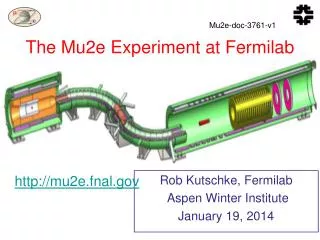
mu2e Muon Beam and Detector for every incident proton 0.0025 m-’s are stopped in the 17 0.2 mm Al target foils MECO spectrometer design
Production Region • Axially graded 5 T solenoid captures low energy backward and reflected pions and muons, transporting them toward the stopping target • Cu and W heat and radiation shield protects superconducting coils from effects of 50kW primary proton beam Superconducting coils 2.5 T 5 T Proton Beam Heat & Radiation Shield Production Target
Transport Solenoid • Curved solenoid eliminates line-of-sight transport of photons and neutrons • Curvature drift and collimators sign and momentum select beam • dB/ds < 0 in the straight sections to avoid trapping which would result in long transit times Collimators and pBar Window 2.1 T 2.5 T
Detector Region • Axially-graded field near stopping target to sharpen acceptance cutoff. • Uniform field in spectrometer region to simplify momentum analysis • Electron detectors downstream of target to reduce rates from g and neutrons Straw Tracking Detector Stopping Target Foils 2 T 1 T 1 T Electron Calorimeter
Magnetic Field Gradient Production Solenoid Transport Solenoid Detector Solenoid
Transported Particles Vital that e- momentum < signal momentum E~3-15 MeV
Tracking Detector/Calorimeter • 3000 2.6 m straws • s(r,f) ~ 0.2 mm • 17000 Cathode strips • s(z) ~ 1.5 mm • 1200 PBOW4 cyrstals in electron calorimeter • sE/E ~ 3.5% • Resolution: .19 MeV/c
Rme = 10-16 gives 5 events for 4x10²⁰ protons on target 0.4 events background, half from out of time beam, assuming 10-9 extinction Half from tail of coherent decay in orbit Half from prompt Sensitivity Coherent Decay-in-orbit, falls as (Ee-E)5
Enter Fermilab • Fermilab • Built ~1970 • 200 GeV proton beams • Eventually 400 GeV • Upgraded in 1985 • 900GeV x 900 GeV p-pBar collisions • Most energetic in the world ever since • Upgraded in 1997 • Main Injector-> more intensity • 980 GeV x 980 GeV p-pBar collisions • Intense neutrino program • Will become second most energetic accelerator (by a factor of seven) when LHC comes on line ~2009 • What next???
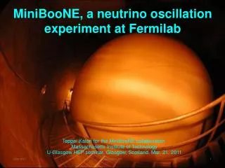
The Fermilab Accelerator Complex MiniBooNE/BNB NUMI
microBooNE, August 20th, 2007 - Prebys Preac(cellerator) and Linac “New linac” (HEL)- Accelerate H- ions from 116 MeV to 400 MeV “Preac” - Static Cockroft-Walton generator accelerates H- ions from 0 to 750 KeV. “Old linac”(LEL)- accelerate H- ions from 750 keV to 116 MeV
Booster • Accelerates the 400 MeV beam from the Linac to 8 GeV • Operates in a 15 Hz offset resonant circuit • Sets fundamental clock of accelerator complex • From the Booster, 8 GeV beam can be directed to • The Main Injector • The Booster Neutrino Beam (MiniBooNE) • A dump. • More or less original equipment
Main Injector/Recycler • The Main Injector can accept 8 GeV protons OR antiprotons from • Booster • The anti-proton accumulator • The Recycler (which shares the same tunnel and stores antiprotons) • It can accelerate protons to 120 GeV (in a minimum of 1.4 s) and deliver them to • The antiproton production target. • The fixed target area. • The NUMI beamline. • It can accelerate protons OR antiprotons to 150 GeV and inject them into the Tevatron.
Present Operation of Debuncher/Accumulator • Protons are accelerated to 120 GeV in Main Injector and extracted to pBar target • pBars are collected and phase rotated in the “Debuncher” • Transferred to the “Accumulator”, where they are cooled and stacked • Not used for NOvA
Available Protons: NOvA Timeline Roughly 6*(4x1012 batch)/(1.33 s)*(2x10⁷ s/year)=3.6x1020 protons/year available MI uses 12 of 20 available Booster Batches per 1.33 second cycle Preloading for NOvA Recycler Recycler MI transfer Available for 8 GeV program 15 Hz Booster cycles MI NuMI cycle (20/15 s)
Delivering Protons: “Boomerang” Scheme • Deliver beam to Accumulator/Debuncher enclosure with minimal beam line modifications and no civil construction. MI-8 -> Recycler done for NOvA Recycler(Main Injector Tunnel) New switch magnet extraction to P150 (no need for kicker)
Energy T=0 1st batch is injected onto the injection orbit T<66ms 1st batch is accelerated to the core orbit T=67ms 2nd Batch is injected 2nd Batch is accelerated 3rd Batch is injected Momentum Stacking • Inject a newly accelerated Booster batch every 67 mS onto the low momentum orbit of the Accumulator • The freshly injected batch is accelerated towards the core orbit where it is merged and debunched into the core orbit • Momentum stack 3-6 Booster batches T<133ms T=134ms
Rebunching in Accumulator/Debuncher Momentum stack 6 Booster batches directly in Accumulator (i.e. reverse direction) Capture in 4 kV h=1 RF System. Transfer to Debuncher Phase Rotate with 40 kV h=1 RF in Debuncher Recapture with 200 kV h=4 RF system st~40 ns
Exploit 29/3 resonance Extraction hardware similar to Main Injector Septum: 80 kV/1cm x 3m Lambertson+C magnet ~.8T x 3m Resonant Extraction
Requires new building. Minimal wetland issues. Can tie into facilities at existing experimental hall. Proposed Location
Three Types of Backgrounds 1. Stopped Muon Induced Backgrounds • Muon decay in orbit: m-→ e-nn • Ee < mmc2 – ENR – EB • N (E0 - Ee)5 • Fraction within 3 MeV of endpoint 5x10-15 • Defeated by good energy resolution • Radiative muon capture: m-Al→ gnMg • g endpoint 102.5 MeV • 10-13 produce e- above 100 MeV
Backgrounds (continued) 2. Beam Related Backgrounds • Suppressed by minimizing beam between bunches • Need ≲ 10-9 extinction • Get 10-3 for free • Muon decay in flight: • m-→ e-nn • Since Ee < mmc2/2, pm > 77 GeV/c • Radiative p- capture: • p-N→N*g, gZ → e+e- • Beam electrons • Pion decay in flight: • p-→ e-ne 3. Asynchronous Backgrounds • Cosmic rays • suppressed by active and passive shielding
The Bottom Line Blue text: beam related. Roughly half of background is beam related, and half interbunch contamination related Total background per 4x10²⁰ protons, 2x10⁷ s: 0.43 events Signal for Rme = 10-16: 5 eventsSingle even sensitivity: 2x10-1790% C.L. upper limit if no signal: 6x10-17
Possible Future: “Project X” • Three 5 Hz pulses every 1.4 s Main Injector cycle = 2.3MW at 120 GeV • This leaves four pulses (~200 kW) available for 8 GeV physics • These will be automatically stripped and stored in the Recycler, and can also be rebunched there.
Experimental Challenges for Increased Flux • Achieve sufficient extinction of proton beam. • Current extinction goal directly driven by total protons • Upgrade target and capture solenoid to handle higher proton rate • Target heating • Quenching or radiation damage to production solenoid • Improve momentum resolution for the ~100 MeV electrons to reject high energy tails from ordinary DIO electrons. • Limited by multiple scattering in target and detector planes • Requirements at or beyond current state of the art. • Operate with higher background levels. • High rate detector • Manage high trigger rates • All of these efforts will benefit immensely from the knowledge and experience gained during the initial phase of the experiment. • If we see a signal a lower flux, can use increased flux to study in detail • Precise measurement of Rme • Target dependence • Comparison with meg rate
However, the future has some uncertainty! (from Dep. Director Y-K Kim)
Conclusions • We have proposed a realistic experiment to measure • Single event sensitivity of Rme=2x10-17 • 90% C.L. limit of Rme<6x10-17 • ANY signal = Beyond Standard Model physics • This represents an improvement of more than four orders of magnitude compared to the existing limit, or over a factor of ten in effective mass reach. For comparison • TeV -> LHC = factor of 7 • LEP 200 -> ILC = factor of 2.5 • Potential future upgrades could increase this sensitivity by one or two orders of magnitude • ANY signal would be unambiguous proof of physics beyond the Standard Model • The absence of a signal would be a very important constraint on proposed new models.
Project X Linac Single 3 MW JPARC Klystron “PULSED RIA” Front End Linac 325 MHz 0-110 MeV 0.5 MW Initial 8 GeV Linac Modulator 11 Klystrons (2 types) 449 Cavities 51 Cryomodules Multi-Cavity Fanout at 10 - 50 kW/cavity Phase and Amplitude Control w/ Ferrite Tuners H- RFQ MEBT RTSR SSR DSR DSR Modulator β<1 ILC LINAC 10 MW ILC Multi-Beam Klystrons Modulator Elliptical Option 1300 MHz0.1-1.2 GeV β=.47 β=.47 β=.61 β=.61 β=.61 β=.61 48 Cavites / Klystron 2 Klystrons 96 Elliptical Cavities 12 Cryomodules or… 325 MHz Spoke Resonators β=.81 β=.81 β=.81 β=.81 β=.81 β=.81 8 Cavites / Cryomodule ILC LINAC 8 Klystrons 288 Cavities in 36 Cryomodules 1300 MHz β=1 Modulator Modulator Modulator Modulator 10 MW ILC Klystrons 36 Cavites / Klystron β=1 β=1 β=1 β=1 β=1 β=1 β=1 β=1 β=1 β=1 β=1 β=1 β=1 β=1 β=1 β=1 β=1 β=1 Modulator Modulator Modulator Modulator β=1 β=1 β=1 β=1 β=1 β=1 β=1 β=1 β=1 β=1 β=1 β=1 β=1 β=1 β=1 β=1 β=1 β=1
Helical Cooling Channel A helical cooling channel (similar to a “Siberian Snake”) provides transverse cooling of muon beam: This, together with an ionizing degrader could allow the forward muons to be used, for a much higher efficiency.