Download
1 / 33
330 likes | 501 Views
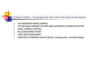
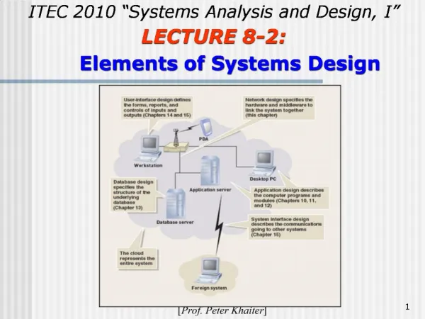
Info 1409 Systems Analysis & Design Module Lecture 8 – Modelling tools and techniques. HND Year 1 2008/9 De Montfort University. Objectives. The objectives of this lecture are to explain CASE tools Unified modelling language Use Case diagrams. Lecture objectives.

E N D
Info 1409 Systems Analysis & Design ModuleLecture 8 – Modelling tools and techniques HND Year 1 2008/9 De Montfort University
Objectives The objectives of this lecture are to explain • CASE tools • Unified modelling language • Use Case diagrams
Lecture objectives By the end of this lecture you will: • Understand the need for specialist tools and methods in systems modelling • Have been introduced to Unified Modelling language and its concepts • Understand the need for Use Case models.
Introduction to system modelling Producing the logical view of a system means: • producing graphical models which use non technical language for descriptions. • Representing the system at various stages of development • Charting business processes and requirements and interactions.
CASE tools Computer Aided Software Engineering CASE helps developers design and construct information systems This module will introduce you to a CASE tool in your Lab sessions in term 2
The CASE environment Using a CASE tool can: • Speed up the development process • Plan ‘business driven’ systems • Support the software development process • Produce models and comprehensive documentation Giving an industry standard for all the above tasks.
Definition of CASE tools • As early as the 1960’s programmers used tools such as editors and code debuggers to write programs. • Today we live in a ‘software driven’ world. CASE tools are now powerful resources that systems analysts need in order to build complex information systems.
Definition of a CASE environment by Carnegie Mellon From Shelley et al
CASE terms and concepts • A typical CASE tool is a set of individual software tools that share information in what is called a ‘Repository’ • CASE tools can be used to model, document, engineer and construct the information system • They are software tools which can provide the following functions:
Individual tools 1. Documentation tool The CASE environment builds up a database of information about the system model and can then produce the necessary documentation.
Individual tools (2) 2. Engineering tools These translate business processes into applications, by producing models like Use Case or Data flow diagrams
Individual tools (3) 3. Construction tools- This facility generates code, screen layouts and reports in languages such as Java, C++ and VB)
FourGen offers a screen generator that can create Data entry screens, and forms, program code and reports Illustration by permission from Shelley et al
Future Trends Quote from Shelley Cashman et al (p551) “Traditional CASE software evolved from functional tools (such as code editors) to help developers envision and construct an entire information system”
Future Trends Quote from Shelley Cashman et al (p551) “ It is predicted that the next generation of CASE tools will go even further, working with internal and external business processes for organisations”.
Unified Modelling language What is Unified modelling language….? Before proceeding, we really need to know.
Activity time To answer this questionwe aregoing to discuss and brainstorm. You need to group in 3’s for this one
Some facts to help you • UML is just a syntax. It says nothing about how too create a model • UML is well documented but little understood • It was developed by Grady Booch, Jim Rumbaugh and Ivar Jacobon at Rational Software • UML specifies 8 different diagrams. Not all are used in practice. • A use case diagram shows the functionality of the system from the ‘outside in’ • Class diagrams show the static structure of the systems
Activity time (Brainstorming) Think about and talk about how you might answer the following question: What IS Unified Modelling Language and what is if for?
Unified modelling language is.. Give your definitions here:
UML Benefits UML : • Uses Object Oriented design concepts • Is a popular method of visualising and documenting software systems. • Is independent of any specific programming language
Benefits of Unified Modelling language UML : • Provides graphical tools for example Use Case models • Can represent the info system from Users standpoint.
Use Case Diagrams • During requirements modelling analysts and users together model the system functions • A Use Case diagram visually represents the interaction between Users and the Information system Use Case diagramscan be drawn freehand, or using Case tools.
In this diagram the Actor is a customer and the Use Case is a credit validation performed by the system.
Use Case components cont.. • The Use Case is the function that the Actor (user of the system) wants the system to perform • It is represented by an ellipse with a written description of what the function needs to be. • The line joining the Actor and the Use Case is called an association
Use Case components cont.. • The Actor is represented by a human figure (usually a stick person) • There is a system boundary which is illustrated by the square box in which the activities of the system take place. • Please note that the Actor is external to the system – (at the system interface).
Use Case documentation • It is always necessary to document diagrams in the modelling process. • The reason is that analysts and designers work as a team (with Users and with each other). • A model alone can be subject to interpretation. • A descriptive table to accompany a diagram ensures clarity
This table documents the Credit card validation in the previous example
Use Case functions The successful completion part of the table outlines the activities that make up the functions of the Use Case. • In this case there are 3 • Notice that the three activities consist of an input a process and an output
Activity time • Draw the Use Case example in slide 24. Label its component parts and note down where the inputs/outputs and processes would occur.
In conclusion At the end of this lecture you have: • Been introduced to UML • Learned about the use of CASE tools • Been introduced to modelling techniques • Seen examples of Use Case models • Recognised the need for documentation
Background reading Chapter 3 – Modelling tools and techniques Pp98-100 Part 5 of the Systems Analysis Toolkit from Systems Analysis & Design. Shelley Cashman and Rosenblatt 6th/7th Edition Thomson Course Technology 2006/7