Download
1 / 18
210 likes | 547 Views
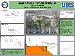
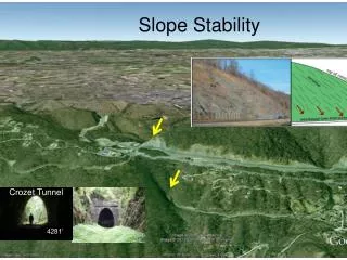
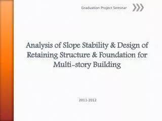
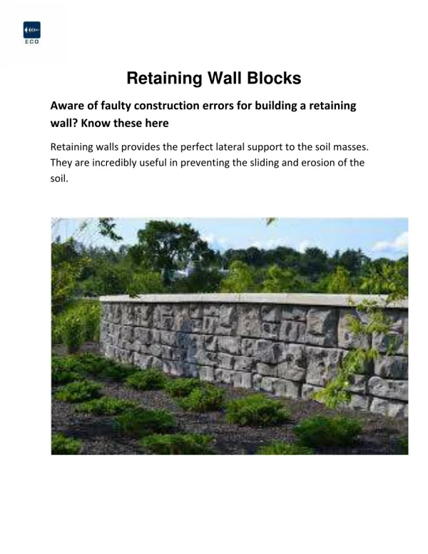
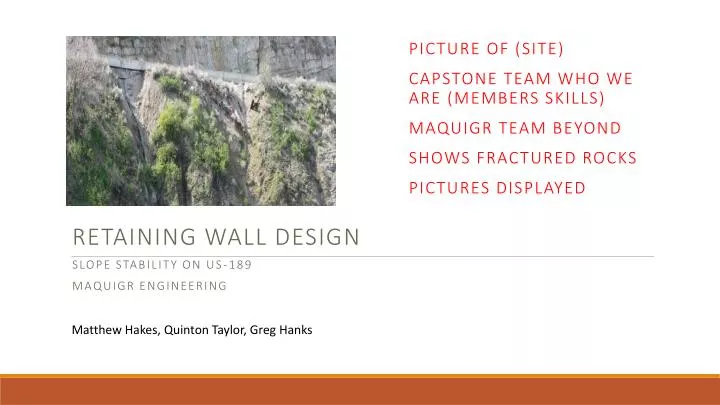
Picture of (site) Capstone Team Who we are (Members skills) Maquigr team beyond Shows fractured rocks Pictures displayed . Retaining Wall Design Slope Stability on US-189 MAQuiGr Engineering. Matthew Hakes, Quinton Taylor, Greg Hanks. Site 1. Site Evaluation. Site 2.

E N D
Picture of (site) Capstone Team Who we are (Members skills) Maquigr team beyond Shows fractured rocks Pictures displayed Retaining Wall Design Slope Stability on US-189 MAQuiGrEngineering Matthew Hakes, Quinton Taylor, Greg Hanks
Site 1 Site Evaluation Site 2 Site 1 is featured on top Site 2 on bottom Notice: Water location Temporary solutions Loads caused by road
Considered Solutions Sheet pile Pros Rapid Construction Cons Shallow rock makes it impossible to dig in deep enough to get moment Gabion Tieback Sheetpile Tieback Shotcrete Soil Nail
Analysis with SnailPlus Assumptions made: • Two different soil types • Gravel/Sand • Bedrock • Loading • Temporary Max: 700 psf from construction • Permanent Max: 200 psf from traffic • Morgenstern-Price • General limit equilibrium (Moment-force) • FHWA factors of safety used
Analysis with SnailPlus • Under construction loading conditions • Under normal traffic loads
Final Design • 10ft from road edge • 120ft in length • 17 Total Soil Nails Initial conception of wall shape Created slope in AUTO cad Unified design 1/2 the distance Follow slope or what Optimized for construction • Average height, 6ft • Max height, 13ft
Phase 1 Site Preparation • Conducted during low traffic flow • Close southbound lane • Flaggers to direct flow of traffic through single lane Environmental Impact Reduction (3 lines of defense) • Excavated 5ft bench • 1ft silt fence installed 20ft below excavation line • Exposed Shoreline
Phase 2 Excavation Slope Preparation • 5ft bench approximately 10ft out from edge of the road • Excavation of 1,000 cubic feet • Soil relocated to holding site
Soil Nail Installation Phase 3 • Williams Geo-Drill Injection Anchor System with rotary percussive drilling • In case of hitting hard rock, a Polyester Resin Rock Anchor System may be used
Phase 4 Prefabrication of Rebar Cages • Phase 4: • Constructed offsite due to limited space • 75 year design life, hot-dip galvanizing
Installing Rebar Cages Phase 5 • Challenge will be mobility and visibility of excavator • Guided into place by multiple workers located on bench The key to the project was contstruction speed 8 in mat Number 6 rebar Tied together Bring in on flat bead and then drop in excavator secure them in place
Shotcrete Phase 6 • Two step process using wire mesh as backstop for shotcrete • First day application spraying towards the road, second day other side is applied A problem (wall needs concrete) solution we could pump it with shotcrete Bench was created for workers to stand on No wall – wire mesh 2 sided
Installing Drainage System Phase 7 Phase 5: • Composite Drainage system • Drainage system includes: geosythetic filtered fabric and molded plastic core
Anchor to wall Attachments Phase 8 • Bearing plate, hardened washers, hex nut, and Geo-Drill Injection Anchor • 75 year design life, galvanizing bearing plate and hardened washers and capped with a steel tube filled with cement grout
Phase 9 Backfill • Using the soil from the excavation, backfill at 8-12in lifts • Compact soil with plate compactor attachment while avoiding soil nails • Increased bar size to improve bending strength in the case of accidental contact with compactor
Capping Phase 10 Phase 11 Cleanup • Phase 10: • Last 4-6in of backfill will be filled with cement to cap off the retaining system • Reduce permeability of surface and prevent corrosion Phase 11: • Remove silt fencing and any loose material • Add soil to bench to create a more natural slope • Application of hydroseed to slope to promote vegetation growth
Time and Cost Estimates Cost The Federal Highway administration Charcteristics that cost $$$ Location, material, night time ect Schedule How we came up Integrating phases to opomize time • Cost estimates are based on the FHWA pricing graph and scheduling was created in 11 phases
Conclusion A soil nail retaining system is the best option for this project • Adaptable – Depending on what is encountered during construction this design can easily be modified to meet the needs of the project • Cost Effective – With little excavation near the road, a temporary wall will be unnecessary • 75 Design Life – Simple methods that can be implicated to increase design life