LPOL-cavity
LPOL-cavity. Mechanics Test cavity (pb of the gain) Optics (laser polarisation) Electronics & DAQ Z. Zhang’s talk. Gain 8000. Fabry-Perot cavity: principle. e beam. L. Polar. Circ. Polar. Lin. When n Laser = n 0 c/2L r e sonance.

LPOL-cavity
E N D
Presentation Transcript
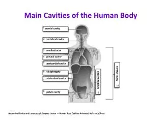
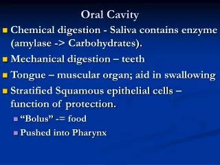
LPOL-cavity • Mechanics • Test cavity (pb of the gain) • Optics (laser polarisation) • Electronics & DAQ Z. Zhang’s talk
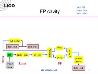
Gain 8000 Fabry-Perot cavity: principle e beam L Polar. Circ. Polar. Lin. When nLaser =n0c/2Lresonance • But :Dn/nLaser = 10-11 laser/cavity feedback • Done by changing the laser frequency • Laser: Nd:YAG (infrared, l =1064 nm)
inside laser Ionic pumps bellow Beam pipe laser Mirror mount Mirror mount amortisseurs
Mount for travel Final cavity
Beam pipe Bellow ‘laser axis’
Beam pipe & laser tube inside cavity Holes for vacuum conductivity
Mirror mounts: On the optical table & isolated from cavity & beam pipe rotation cavity mirror bellow Orientations (‘gimbolt’): ‘plan/line/point’ system
Test cavity at orsay Vacuum pump Motorised mirrors Mirror mounts CCD Laser ND:YAG Optcal room Temperature: 0.5o Photodiode feedback (Saclay)
P-diode laser glan cavity nlaser Data (oscillo) 2Hz & 10V pic-pic Ramp fit V Intensity reflected zoom Intensity transmited Dnlaser=75MHz (nlaser=3.108MHz) t(oscillo)/s t(oscillo)/s 200 ms 100 ms Mirror Laser Under investigation gain cavity test 2000/8000
Beam intensity after cavity (Gaussian in principle) Intensity (beam scan measure) x y
Zoom : Slope not symetric bump
Ellipsometry (`classic’) : Quarter wave plate cavity degree of circular polarisation after cavity • such :(I1-I2)/(I1+I2) = • Quart wave plate is the most sensitive element … :- • Choice & calibration importants for a per mill precision measurement …
f 50 kHz 12 bits ADC Linear polarised light p-diode:I1 10 mW YAG Laser l/4 Glan Thomson p-diode:I0 I1/I0 <0.25% I1/volts 2% In practice … f/deg choice l/4anti-reflec. coated f In principle n2 1.90, d2 50 nm n1 1.36, d1 238 nm Quartz, <n> 1.54, d 150 m
R/% -20 nm • Reflection coef. at normal incidence • Choice of an uncoated l/4plate • But model required … d2 d1 +20 nm Transmitted field Depends on thickness & optical indices no & ne. Quartz = Anisotropic uniaxial medium 4 directions for the field E (2GO & 2BACK)
Polar vertical Calibration of the Quartz plate p-diode I1 Polar vertical f 10 mW YAG Laser l/4 Wollaston cube p-diodeI2 Glan Thomson Polar elliptic p-diode I0 Polar horizontal • Performances Wollaston & Glan Thomson : 10-5 (verified) • Measurements of I1/I0 et I2/I0 as function of f for différent incident angles fit no, ne & thickness
Photodiode readout • Sequence of measurements(ADC 12bits, 50kHz, [-50mV,50mV] range) • Laser off (beam shutter) 10k-20k evts/angle • Pedestals of the 3 diodes = br0, br1, br2 • Laser on : 10k-20k evts/angle • Int. for the 3 diodes: • I0=Int1-br0, I1=Int1-br1, I2=Int2-br2 • I1/I0, I2/I0 recorded evt by evt to compensate for laser variations
70 mV 15 mV 12 mV Fixed angle DT= 0.2o 1.4 mV pedestals 26 h
20 min periode 100% correlated with Temperature Same plots For 2h
Diode 0 Glan Thomson Wedge plate Diode 1 & 2 Wollaston L/4: 6 m-metric screws
Plans • We checked that Temp. variations come from pdiode analog electronics • Long term variations (24h periode) not understood… • Use Temperature stable preamps for photodiodes(now fast preamps of feedback pdiode are used…) • Other solution: analog switching same preamp for the 3 diodes Precision better than 0.1%
c2 < 50 nm/150 mm c2 De/mm < 0.1% c2 Dno < 0.1% Dne f Results (prel.) f Pate auto-calibration by Interferometry • Laser polar controled at 0.1% level for HERA already • no(T) & ne(T) for ND:YAG in handbooks are computed ! mesurement at the per mill level
Conclusions • Mechanics: • cavity arrived beg. july at Orsay • August-sept: vacuum tests • Optical mounts and cavity mirror mounts • Being done in LAL workshop (finished in sept.) • Feedback and cavity gain • Still low, investigations being done & wait the final system for more more tests (mirror alignment syst. variations) • Laser polarisation • Per mill level almost reached after 1 year of work… • Test of the final setup: start in september
Feedback nL nL-930kHz nL+930kHz 4MHz/Volt (nL =3.108 MHz) YAG laser Glan Cavity nC=nc/(2L) piezo gene Reflected signal Ramp + sin 930 kHz Photodiode Interference between central & side bandes Servo (analog elec) X Correction signal (closed loop=ramp off) V nL – nC whennLnC
4 mirrors Cavité de test au LAL: Schéma optique Signal refléchi feedback lens Pockels cell Glan thomson lens l/2 plate Faraday isolator laser hublot
Implémentation à HERA et `électronique’ • Laser et éléments optiques sont près de la cavité s fini En cours de réalisation