Structural Analysis II
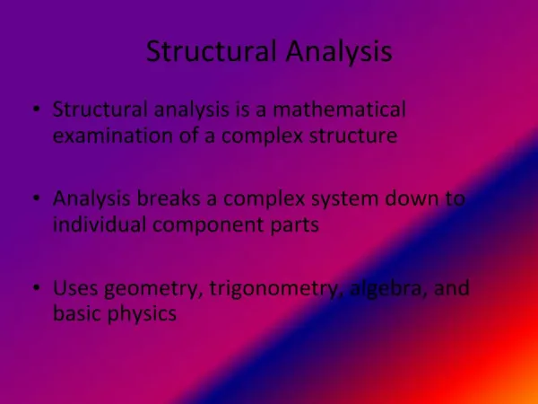
Structural Analysis II. Structural Analysis Trigonometry Concepts Vectors Equilibrium Reactions Static Determinancy and Stability Free Body Diagrams Calculating Bridge Member Forces. Learning Objectives. Generate a free body diagram

Structural Analysis II
E N D
Presentation Transcript
Structural Analysis II • Structural Analysis • Trigonometry Concepts • Vectors • Equilibrium • Reactions • Static Determinancy and Stability • Free Body Diagrams • Calculating Bridge Member Forces
Learning Objectives • Generate a free body diagram • Calculate internal member forces using the Method of Joints
Free Body Diagram • Key to structural analysis • Draw a simple sketch of the isolated structure, dimensions, angles and x-y coordinate system • Draw and label all loads on the structure • Draw and label reactions at each support
Structural Analysis Problem • Calculate the internal member forces on this nutcracker truss if the finger is pushing down with a force of eight newtons.
y c x 40o 12 cm 70o 70o b a Structural Analysis SolutionDraw the Free Body Diagram Step 1: Draw simple sketch with dimensions, angles, and x-y coordinate system Nutcracker truss formed by tied ends Corresponding sketch
8N y c 12 cm x 40o 70o 70o a b Structural Analysis SolutionDraw the Free Body Diagram Nutcracker truss with 8N load Step 2: Draw and label all loads on the structure Added to free body diagram
8N y c 12 cm x 40o 70o 70o b a Ra Rb Structural Analysis Solution Draw the Free Body Diagram • The truss is in equilibrium so there must reactions at the two supports. They are named Ra and Rb. Step 3: Draw and label all reactions at each support
Structural Analysis Solution Method of Joints • Use the Method of Joints to calculate the internal member forces of the truss • Isolate one joint from the truss • Draw a free body diagram of this joint • Separate every force and reaction into x and y components • Solve the equilibrium equations • Repeat for all joints
y 8N 12 cm x c 40o y c 70o 70o Fac 70o b a Fab a b x Ra = 4N Ra = 4N Rb = 4N Structural Analysis Solution Method of Joints Step 1: Isolate one joint Step 2: Draw the free body diagram
y a x Ra = 4N Structural Analysis Solution Method of Joints First analyse Ra • x-component = 0N • y-component = 4N Step 3: Separate every force and reaction into x and y components
y Fab a b x Structural Analysis Solution Method of Joints Next analyse Fab • x-component = Fab • y-component = 0N Step 3: Separate every force and reaction into x and y components
y c Fac 70o a x Structural Analysis Solution Method of Joints Lastly, analyse Fac • x-component = Fac*cos70˚ N • y-component = Fac*sin70˚ N Step 3: Separate every force and reaction into x and y components
y y a x c Ra = 4N Fac 70o a x Summary of Force Components, Node ‘a’ y x Fab
Structural Analysis Solution Method of Joints • The bridge is not moving, so ΣFy = 0 • From the table, ΣFy = 4N + Fac * cos70˚ = 0 • Fac = ( -4N / cos70˚ ) = -4.26N • Internal Fac has magnitude 4.26N in compression Step 4: Solve y-axis equilibrium equations
Structural Analysis Solution Method of Joints • The bridge is not moving, so ΣFx = 0 • From the table, ΣFx = Fab + Fac * sin70˚ = 0 Fab = - ( -4.26N / sin70˚ ) = 1.45N • Internal Fab has magnitude 1.45N in tension Step 4: Solve x-axis equilibrium equations
Structural Analysis Solution Method of Joints Tabulated Force Solutions
y 12 cm 8N x y 40o c 8N 70o 70o c x Fac = -4.26N Fbc 40o b a a b Ra Rb Structural Analysis Solution Method of Joints Step 5: Repeat for other joints Step 1: Isolate one joint Step 2: Draw the free body diagram
y 8N c x Structural Analysis Solution Method of Joints First analyse Rc • y-component is -8N • x-component is 0N Step 3: Separate every force and reaction into x and y components
y c x Fac 20o a Structural Analysis Solution Method of Joints Step 3: Separate every force and reaction into x and y components Next analyse Fac • x-component is –(Fac * sin20˚) = - (-4.26N * 0.34) = 1.46N • y-component is –(Fac * cos20˚) = - (-4.26N * 0.94) = 4.00N
y c x Fbc 20o b Structural Analysis Solution Method of Joints Lastly analyse Fbc • y-component = –(Fbc * cos20˚) • x-component = (Fbc * sin20˚) Step 3: Separate every force and reaction into x and y components
8N c c Fbc 20o b Summary of Force Components, Node ‘c’ c Fac 20o a
Structural Analysis Solution Method of Joints • The bridge is not moving, so ΣFy = 0 • From the table, ΣFy = -8.00N + 4.00N - Fbc * cos20˚ = 0 Fbc = -4.26N • Internal Fbc has magnitude 4.26N in compression Step 4: Solve y-axis equilibrium equations
Structural Analysis Solution Method of Joints • The bridge is not moving, so ΣFx = 0 • From the table, ΣFx = 1.46N + Fbc * sin20˚ = 0 Fbc = -4.26N • This verifies the ΣFy = 0 equilibrium equation and also the symmetry property Step 4: Solve x-axis equilibrium equations
Structural Analysis Solution Method of Joints Tabulated Force Solutions
Acknowledgements • This presentation is based on Learning Activity #3, Analyze and Evaluate a Truss from the book by Colonel Stephen J. Ressler, P.E., Ph.D., Designing and Building File-Folder Bridges