Wide area network (WAN)
1.03k likes | 2.16k Views
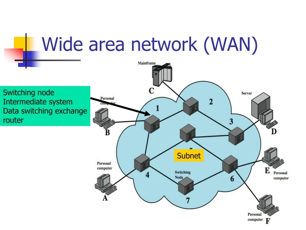
Wide area network (WAN). Switching node Intermediate system Data switching exchange router. Subnet. Circuit-switched network (PSTN). Creates a direct physical connection Provides a fixed data rate channel. Circuit-switched network (PSTN). uses a dedicated path between two stations

Wide area network (WAN)
E N D
Presentation Transcript
Wide area network (WAN) Switching node Intermediate system Data switching exchange router Subnet
Circuit-switched network (PSTN) Creates a direct physical connection Provides a fixed data rate channel
Circuit-switched network (PSTN) • uses a dedicated path between two stations • has three phases • establish • transfer • disconnect • inefficient • channel capacity dedicated for duration of connection • if no data, capacity wasted • set up (connection) takes time • blocking network • Constant data rate
Hook switch & Ringer On-hook - 48 V Ringing signal 75-90 Vrms f=18-25 Hz
Hook switch • Off-hook
วงจร Hybrid • 2w to 4w • Side tone
Dialing • Pulse Dialing • ส่ง pulse มีจำนวนเท่ากับเลขที่หมุน • Dual Tone Multifrequency dialing (DTMF)
Local Network • Subscriber terminal • Drop wire • จุดกระจายสาย DP • ตู้พักสาย CCP • MDF • Switching • ชุมสายท้องถิ่น • TDF • ชุมสายต่อผ่านท้องถิ่น
Public data network (PDN) • Circuit switched (PSTN) • Packet switched • X.25, 64kbps • Frame Relay, up to 2 Mbps • Cell relay • Asynchronous Transfer Mode (ATM), up to 622.08 Mbps
Packet switching • circuit switching was designed for voice • packet switching was designed for data • transmitted in small packets • No physical connection is established through a PSPDN • Packet store & Forward at intermediate Packet switching exchanges (PSE) • At the destination PSE the packet is delivered to the destination DTE
Advantages • line efficiency • single link shared by many packets over time • packets queued and transmitted as fast as possible • data rate conversion • stations connects to local node at own speed • nodes buffer data if required to equalize rates • packets accepted even when network is busy • priorities can be used
Packet switching • Datagram approach (Letter) • Virtual circuit approach (telephone call) • SVC (switched) • PVC (Permanent)
Datagram approach • Each packet is treated independently
Virtual circuit approach • A single route is chosen between sender and receiver • All packets of the transmission travel one after another along that route • The link that make a route can be shared by other connections
SVC • Comparable conceptually to dial-up lines in circuit switching
Permanent VC • Comparable to leased lines in circuit switching (No need for call set-up)
X.25 • Packet-switching wide area network (ITU-T,1976) • 64 kbps Router
Frame layer (Link access protocol, balanced LAPB) • Subset of HDLC • Making a connection between DTE &DCE
Addressing at the frame layer • Point-to-point, asynchronous balanced mode
Packet layer protocol (PLP) • Create the virtual circuit • End-to-end connection • End-to-end flow and error control
Virtual circuits in X.25 • A physical connection can carry several virtual circuits at a network layer (Multiplexing)
Frame Relay • designed to eliminate most X.25 overhead • call control carried in separate logical connection • multiplexing and switching at layer 2 • No error control or flow control • hence end to end flow and error control (if used) are done by higher layer • a single user data frame is sent from source to destination and higher layer ACK sent back
Advantages and Disadvantages • lost link by link error and flow control • increased reliability means less an issue • streamlined communications process • lower delay • higher throughput • frame relay can be used for access speeds up to and over 2Mbps
User Data Transfer Flag Address Information FCS Flag • only have one frame type which carries user data • flag and FCS function as in HDLC • address field carries DLCI • DLCI (Data Link Connection Identifier), the same function as the virtual circuit number in x.25
Packet network multiplexing Different packet sizes
Cell network multiplexing A cell is a small, fixed-sized block of information
Asynchronous transfer mode (ATM) Asynchronous TDM
Protocol Architecture ITU-T
ATM adaptation layer (AAL) Service classification for AAL
AAL sublayers • Convergence (CS) • Support specific applications • Segmentation and reassembly (SAR)
AAL 5 Higher layer PDU CPCS-PDU payload Pad CPCS-T CS CPCS-UU CPI Length CRC 48-byte block SAR ATM-H ATM cell
ATM layer • Connection-oriented • No acknowledgement • Cell sent along a virtual circuit will never arrive out of order
ATM Virtual Path Connection • virtual path connection (VPC) • bundle of channel connection (VCC) with same end points
1 1 3 4 2 2 UNI NNI 4 3 UNI=User-network interface NNI=Network-network interface
1 1 3 4 2 2 UNI NNI 4 3 UNI=User-network interface NNI=Network-network interface
ATM Header Fields • generic flow control • Virtual path identifier • Virtual channel identifier • payload type • cell loss priority • header error control
Payload Type (PT) field indicates the type of information in the information field. A value of 0 in the first bit indicates user information. In this case, the second bit indicates whether congestion has been experienced • cell loss priority (CLP) A value of 0 indicates a cell of relatively higher priority, which should not be discarded unless no other alternative is available. A value of 1 indicates that this cell is subject to discard within the network. • Header Error Control (HEC) • 32 header bits, CRC (x8+x2+x+1) • The constant 01010101 is added
Transmission of ATM Cells • I.432 specifies several data rates: • 622.08Mbps • 155.52Mbps • 51.84Mbps • 25.6Mbps
Cell Based Physical Layer • no framing imposed • continuous stream of 53 octet cells • cell delineation based on header error control field