Download
1 / 16
180 likes | 415 Views
Failure Modes and Effects Analysis (FMEA) identifies equipment failure modes and their effects on systems or plants. Learn how FMEA can enhance equipment reliability and process safety. Discover the resource requirements and steps in performing FMEA.

E N D
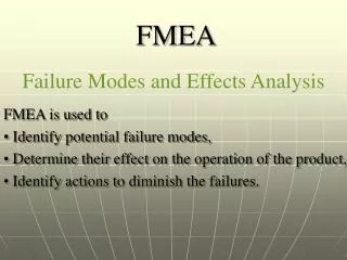
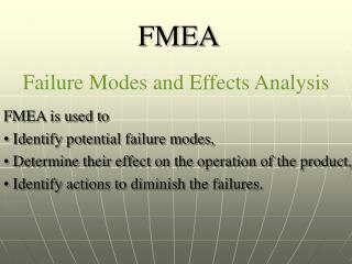
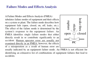
Failure Modes and Effects Analysis A Failure Modes and Effects Analysis (FMEA) tabulates failure modes of equipment and their effects on a system or plant. The failure mode describes how equipment fails (open, closed, on, off, leaks, etc.). The effect of the failure mode is determined by the system’s response to the equipment failure. An FMEA identifies single failure modes that either directly result in or contribute significantly to an accident. Human operator error are usually not examined directly in an FMEA; however, the effects of a misoperation as a result of human error are leaks thru rupture sticks open closed FC usually indicated by an equipment failure mode. An FMEA is not efficient for identifying an exhaustive list of combinations of equipment failures that lead to accidents.
Purpose The purpose of an FMEA is to identify single equipment and system failure modes and each failure mode’s potential effect(s) on the system or plant. This analysis typically generates recommendations for increasing equipment reliability, thus improving process safety. Types of Results An FMEA generates a qualitative, systematic reference list of equipment, failure modes, and effects. A worst-case estimate of consequences resulting from single failure is included. The FMEA may be easily updated for design changes or system/plant modifications. FMEA results are usually documented in a column- format table. Hazard analysts usually include suggestions for improving safety in appropriate items in the table.
Examples of Equipment Failure Modes Used in an FMEA Equipment Description Example Failure Modes Pump, normally operating • Fails on (fails to stop when required) • Transfers off (stops when required to run) • Seal leak/rupture • Pump casing leak/rupture Heat exchanger, high pressure on • Leak/rupture, tube side to shell side tube side • Leak/rupture, shell side to external environment • Tube side, plugged • Shell side, plugged • Fouling
Resource Requirements Using the FMEA approach requires the following data and information sources: a system or plant equipment list or P&ID, knowledge of equipment function and failure modes, and knowledge of system or plant function and responses to equipment failures. FMEAs can be performed by single analysts, but these analyses should be reviewed by others to help ensure completeness. Staff requirements will vary with the size and complexity of equipment functions and failure modes and how the failures might affect other portions of the system or plant. The time and cost of an FMEA is proportional to the size of the process and number of components analyzed. On the average, an hour is sufficient for analyzing two to four equipment items. As with any HE study of systems with similar equipment performing similar functions, the time requirements are reduced significantly due to the repetitive nature of the evaluations. Table 4.8 lists estimates of the time needed to perform an HE study using the FMEA technique.
Analysis Procedure (1)defining the study problem, (2)performing the review, and (3)documenting the results.
STEP 1 : Defining the study problem. This step identifies the specific items to be included in the FMEA and the conditions under which they are analyzed. Defining the problem involves (1)establishing an appropriate level of resolution for the study and (2)defining the boundary conditions for the analysis. A detailed problem definition is a necessary ingredient to performing a thorough and efficient FMEA.
(2)Defining the analysis boundary conditions includes: • Identifying the plant and/or systems that are the subject of the analysis. • Establishing the physical system boundaries for the FMEA. This includes the interfaces with other processes and utility/support systems. One way to indicate the physical system boundaries is to mark them on a system drawing that encompasses all equipment within the scope of the FMEA. These boundary conditions should also state the operating conditions at the interfaces. • Establishing the system analytical boundaries, including: (1)the failure modes, operating consequences, causes, or existing safeguards that will not be considered and (2)the initial operating condition or position of equipment. As an example of effects beyond the scope of the study, an analyst may choose not to consider airplane crashes, earthquakes, or tornadoes as causes of failure modes. An example of an initial condition is specifying whether a valve is normally open or closed. • Collecting up-to-date reference information that identifies the equipment and its functional relationship to the plant/system. This information is needed for all equipment included within the system boundary and appropriate interfaces with the rest of the plant.
FMEA-PC (Primatech, Inc, Columbus, Ohio) HAZOOPtimizer (A. D. Little, Cambridge, Massachusetts) SAFEPLAN (Du Pont, Westlake Village, California) Standard word processing and spreadsheet software programs can also help analysts document the results of FMEA studies.
Example Using the DAP reaction system presented in the Checklist Analysis example (Section 6.2), an FMEA study is performed to address safety hazards to plant personnel. The DAP process schematic is repeated here as Figure 6.7; readers should refer to Section 6.2 for the description of the DAP process. Each component of the reaction system is evaluated with the relevant information recorded in an FMEA table. The section of the FMEA table for Control Valve B in the phosphoric acid solution line is presented in Table 6.21.
UNLOADING STATIONS UNLOADING STATIONS ~ ~ AMMONIA SOLUTION STORAGE TANK PHOSPHORIC ACID STORAGE TANK L1 L1 F1 F1 ENCLOSED WORK AREA OUTDOORS ~~~~~~~~~~~~~~~~ LOADING STATIONS DAP STORAGE TANK Figure 6.7 DAP process schemativ for the FMEA example. Diammonium phosphate (DAP)
PHOS. ACID excess off-spec. Product NH3 excess residual NH3 release BOTH excess T P
Table 6.21 Sample Pages from the FMEA Table for the DAP Process Example