Download
1 / 51
520 likes | 573 Views
This report covers the performance and upgrades of the DAFNE accelerator, focusing on achieving higher luminosity and beam dynamics improvements for future experiments.

E N D
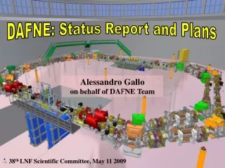
DAFNE: Status Report and Plans Alessandro Gallo on behalf of DAFNE Team 38th LNF Scientific Committee, May 11 2009
DAΦNE Commissioning Team D.Alesini, M.E. Biagini, C.Biscari, A. Bocci, R.Boni, M.Boscolo, F.Bossi, B. Buonomo, A.Clozza, G.Delle Monache, T. Demma, E.Di Pasquale, G.Di Pirro, A.Drago, A.Gallo, A.Ghigo, S.Guiducci, C.Ligi, F.Marcellini, G.Mazzitelli, C.Milardi, F.Murtas, L.Pellegrino, M.A.Preger, L.Quintieri, P.Raimondi, R.Ricci, U. Rotundo, C.Sanelli, M.Serio, F.Sgamma, B.Spataro, A.Stecchi, A.Stella, S.Tomassini, C.Vaccarezza, M.Zobov (INFN/LNF, Frascati (Roma)) I.Koop, E.Levichev, S.Nikitin, P.Piminov, D.Shatilov, V.Smaluk (BINP, Novosibirsk) S.Bettoni (CERN, Geneva) P. Valente (INFN-Roma, Roma) K. Ohmi (KEK, Ibaraki) D. Teytelman, (SLAC) N. Arnaud, D. Breton, L. Burmistrov, A. Stocchi, A. Variola, B. Viaud (LAL, Orsay) M. Esposito (Rome University “La Sapienza”, Roma) E. Paoloni (University of Pisa and INFN, Pisa) P. Branchini (University Roma3, Rome)
OUTLINE • Dafne Results at the last LNF Sci-Com meeting ; • How we got there. A brief review of: - Large Piwinski Angle (LPA) + Crab Waist (CW) concept - Dafne hardware upgrade for the Siddharta run - Commissioning issues • Recent activities on the machine to consolidate the LPA+CW results • Updated machine performances • Perspectives and plans in view of the KLOE-2 run • Conclusions
DAΦNE Performances at Dec. 1st 2008 (37st LNF Scientific Committee Meeting) • Peak Luminosity: 3.52e32 obtained with 1.35 Amps e- vs 1.0 Amps e+, 105 Bunches • Peak hourly rate 0.700 pb-1/hour with long coasting (2.5 injections/hour) • Peak Daily rate 11.95 pb-1 with long coasting • Peak 8-hours rate 5 pb-1 with long coasting • Long coasting needed for Siddharta, not for Kloe or Finuda
Performance limitations in the original DAFNE configuration Lpeak ~ 1.6 1032 cm-2 s-1 was the maximum luminosity achieved in the original DANE configuration due to: y Overlap area @ IP y* z • y ~ z to avoid hourglass effect • Long-range beam-beam interactions causing + - reduction limiting I+MAX I-MAX and consequently Lpeak and L∫ • Transverse size enlargements due to the beam-beam interaction z A new conceptual approach was necessary to reach L ~ 1033 => Collision scheme based on Large Piwinski angle and Crab-Waist
Ultra-low emittance Very small β* at IP Large crossing angle “Crab Waist” transformation Small collision area Lower β* is possible NO parasitic crossings NO x-y-betatron resonances A new idea for collisions Tighter focus on beams at IP and a “large” crossing angle (large Piwinski angle) + use a couple of sextupoles/ring to “twist” the beam waist at the IP
Large Piwinski angle • Lowering the βy*(down to the hourglass limit) is the most efficient way to increase the luminosity: • Large Piwinski angle (helpful in reducing the IP spot length and tune shifts) is obtained by small sx - large : • New IR magnetic layout • splitter magnets and compensator solenoids removed • New low- • Sector dipoles around IP rotated • large collision angle ~ 50 mrd • four C type corrector dipoles used to mach the vacuum chamber in the arc
Crab-Waist compensation Collision with large is not a new idea ….. Crab-Waist transformation is ! (P.Raimondi et al., 2006) • Lgeometric gain • x-y synchro-betatron and betatron resonance suppression sextupole (anti)sextupole IP no CW compensation! (3D) with CW compensation! (3D) with CW compensation! no CW compensation! E. Paoloni, SuperB case
BEAM PROFILES @IP AND NEW PARAMETERS DAFNE (KLOE run) DAFNE Upgrade 3 times more luminosity obtained just with 3 times smaller vertical beam
IP • New low- section • low-beta section based • on PM QUADs: • KQD = -29.2 [T/m] • KQF = 12.6 [T/m] • e+ e- vacuum chambers • separate after QD 5.5cm • Aluminum • Window thickness 0.3 mm
Hardware upgrades for Beam Dynamics improvements Various hardware upgrades have been implemented to improve the stored current: • Fast kickers • Feedback upgrade • Lower impedance vacuum chamber • Solenoid Windings
SECOND CROSSING REGION LAYOUT • Second crossing region symmetric with respect to first one (Possibility to use it as an alternative interaction point) • “Half Moon” chamber allows complete beam separation (no 2nd IP)
NEW BELLOWS OLD BELLOW • 6 new bellows for each ring • Shielding based on Be-Cu W strips 0.2 mm thick • lower impedance and better mechanical performance
New Fast Injection Kickers New injection kickers, capable of supporting 5.4 ns pulse lengthto reduce perturbation on stored beam • Expected benefits: • higher maximum • stored currents • Improved stability of colliding beams during injection • less background allowing data acquisition during injection VT VT 3 bunches 50 bunches t t Present pulse length ~150ns FWHM pulse length ~5.4 ns Status: kickers commissioned, new fast pulsers not fully reliable
First Experimental Results: First Evidence of Crab Waist working Crab Sextupoles on all the time since the first time we tested them
First Experimental Results: Bunch Lengthening in the Upgraded Vacuum Chamber Bunch Length Charge Distribution old new
First Experimental Results: Vertical beam-beam Luminosity scan Design is 3.1mm July 2008
Beam Dynamics Issues in the upgraded Collider Commissioning • Some harmful beam dynamics issues have been faced before getting to the expected performances, namely: • A fast coupled-bunch horizontal instability, probably e- cloud driven; • A longitudinal beam shaking originated in the LLRF barycenter feedback induced by: • 50 Hz noise coming from currents circulating in the DAFNE Common Bonding Network (CBN) (affecting also others machine diagnostic devices); • a 2-beams instability occurring at high current when the feedback systems for both beams are switched on at the same time. This effect had never been observed in the past DAFNE runs.
e+ beam, horizontal grow rates, 105 bunches [October 14, 2008] Grow rates are very fast and are linear versus beam Current. Data are taken on the stored beam. During injection e+ beam have an horizontal perturbation and situation becomes worse.
A pragmatic solution • Observing the linearity of the horizontal instability, growing > 70 (1/ms) for Ibeam>800mA • Considering the further energy given to the instability by the injected bunch, kicked in the horizontal plane • We decide to double the feedback power from 500W to 1kW, but we lack power combiners to join other two 250W amplifiers • We decide to test another pickup (to see if less noisy) and to use the spare striplines of the injection kickers • Due to the fact that in this way the feedback betatron phase advance would have to be different from the other system, it has been necessary to implement a second complete horizontal feedback system
New e+ Transverse Horizontal Feedback • The damping rates of the two feedbacks add up linearly • Damping rates measured: • ~100 ms-1 (1 FBKs) fb damps in 30 revolution periods (~10 us) • ~200 ms-1 (2 FBKs) fb damps in 15 revolution periods (~ 5 us) • The power of the H FBK has been doubled
Transverse shunt impedance of the original hor. FBK and new injection kickers Original DAFNE Horizontal Kicker 20 cm stripline Peak Rs 2.1 kΩ BandwidthHWHM 370 MHz New DAFNE Injection Kicker 93 cm tapered stripline Peak Rs 160 kΩ BandwidthHWHM 90 MHz
Hybrid Kicker horizontal fdbk horizontal fdbk e+ ring old pulser old pulser e- ring old pulser old pulser
Growth rates at higher e+ current: the unstable mode changes and becomes slower! The beam current is not limited by the horizontal instability anymore m=-2 m=-3 m=-1
Preliminary results for electron cloud induced coupled bunch instability in e+ ring: Mode spectrum and growth rate 60 equispaced bunches Beam current 1.2 A Growth time ~ 100 turn -1 mode (60-5-1=54)
Conclusions on the horizontal instability • HOM problems (RF cavity, Bellows Scrapers etc...) seem ruled out • Beam current limit in the e+ ring is probably due to an e-cloud induced instability. • The instability strength is reduced by optimizing the orbit in the new dipoles • The instability grow rates show a good agreement with e-cloud model and simulations • Two separate feedback systems for the same oscillation plane work in perfect collaboration adding their damping rates. The second installed FBK benefits of the substantially higher transverse shunt impedance of the new injection kicker striplines. • FB damping time in 4.3 microsecond i.e. in ~13 revolution turns • Further investigations at even higher beam currents can improve the knowledge of the instability behavior
Phase Noise in RF system • One of the principal recognized sources of luminosity limitation was a longitudinal shaking of the positron bunches driven by spurious phase modulations of the e+ RF. They were originated in the “0-mode feedback” system, which is a low level RF sub-system aimed at damping the beam barycentric coherent motion. • Two main sources of spurious modulation have been identified, namely: • 50 Hz (and multiples) line disturbances; • a 2-beams barycentric longitudinal instability appearing at high current when the 0-mode FBK systems were switched turned–on on both beams. • Under this condition the bunches did not fully overlap at the IP, with a consequent reduction of the geometric luminosity and excitation of beam-beam resonances. • Improvements in the DAFNE equipotential network have reduced the amount of line noise in all the systems, including the RF low-level control. • The 2-beams barycentric instability is avoided at moment by operating the machine with only one 0-mode FBK (the e- one) switched-on.
Noise detection on the Ground system • In order to reduce the current circulating in sensible trunks of the bonding network, some of the connections of the mesh have been opened. • Some tests have been performed by the machine technical Team during some brief stop of the DAFNE run. • The current, temporary, configuration has reduced considerably the noise. • The problem should be completely fixed in the next maintenance shutdown when a reshuffling of the power cables has been planned and we are confident to obtain a definitive reduction in circulating currents.
New Klystron Phase Loop to compensate the HV power supply line noise A new RF feedback loop to compensate the phase noise induced by the klystron HV supply ripple has been designed and commissioned on both rings. The residual phase noise is now well below 1° peak-to-peak, preserving the best longitudinal overlaps of the beams at the IP.
1470 1003 4.36E+32 Peak luminosity 105 bunches A luminosity in excess of 4•1032 cm-2s-1 is measured almost in every run when operating the collider in optimized conditions. y(MAX) is a factor ~1.5 higher than the best achieved without Crab-Waist compensation The collider has the same damping time as in the past y(MAX) ~ 0.042
Best hourly integrated luminosity • L∫1 hour = 1.033 pb-1 • High rate injection regime • 105 colliding bunches • Very useful for a future KLOE run { Fast Injection Dec. 16th 2008 Fast injection is not compatible with the SIDDHARTA operations!
Best daily integrated luminosity • L∫day = 15 pb-1 • Long Coasting Regime • 105 colliding bunches • L∫hour = 0.62 pb-1 Feb. 8th 2009
Data averaged on a full day by=9mm, ΦPiw=1.9 Luminosity [1028 cm-2 s-1] LPA alone gives more luminosity by=18mm, ΦPiw=0.6 by=25mm, ΦPiw=0.3
by=9mm, ΦPiw=1.9 Same beam sizes and specific luminosity at low current with an without Crab Sextupoles Specific Luminosity [1028 cm-2 s-1] by=18mm, ΦPiw=0.6 by=25mm, ΦPiw=0.3
Best two fills Luminosity vs Current Product xy(max)=0.042
Crab on/off Specific Luminosity vs Current Product Crab on/off Luminosity vs Current Product
1978 198 487 472 1.31E+32 1.01E+32 Luminosity in weak-weak and strong-weak regime Low currents y ~ 0.020 Jan. 19th 2009 Jan. 9th 2009 Asymmetric currents y ~ 0.0626
20 Bunches in Collision (mod. 4) L > 5x1030 cm-2 s-1 (single bunch) xy = 0.042
Short term developments • Improve vacuum condition in order to get 110 bunches in collision • Systems stability optimization (RF, FBKs) • Optics refinements in order to optimize: Lpeak Lintegrated Beam lifetime Background hitting the experimental detector • Further investigation about the e+ instability source • transfer-lines collimator commissioning • Standard tuning
Mid-term developments • Installation of a new dedicated kicker for the second transverse horizontal feedback in a position with higher x (x = 3 [m] -> 17 [m] ) in order to increase the feedback dynamic range by a factor > 2 • Equip the second transverse horizontal feedback with two power amplifiers providing 500W output (now 250W) • Install modified wigglers to improve beam lifetimes and reduce wall plug power consumption • Install stripline electrodes in the wiggler and dipoles chambers of e+ ring to clear e- cloud
Wiggler modification Due to the finite width of the poles the field rolls off symmetrically with respect to the wiggler axis. The trajectory inside the wiggler oscillates around the wiggler axis with a peak-to-peak amplitude of ≈2 cm, and, since both the beam position and the field change sign from pole to pole, the field derivative with respect to the horizontal position is always the same. Therefore the contributions of the single poles to odd terms in the field seen by the beam add up coherently, while even terms tend to cancel each other. If each pole is shifted in such a way that its axis is placed at the average distance of the trajectory inside the pole itself from the wiggler axis, also the contribution of the odd terms can be minimized, making the whole wiggler almost linear. The poles have been shifted by ±7.3 mm with respect to the wiggler axis. Also, they are now flat (no shims) and separated by 37 mm.
Minimization of the octupole term After modification the octupole term is reduced by ≈ 2 orders of magitude! • Expected benefits: • Improvement of the non linear optics; • Dynamic aperture increase; • Beam lifetime increase; • Same nominal B field with lower current (450 A against 550 A, due to reduction of poles average separation and magnetic circuit length). Wall plug power saving of ≈ 33% !
Stripline electrodes for e-cloud clearing e-cloud in the wiggler and dipole chambers can be removed by stripline electrodes kept at a moderate voltage (< 0.5 kV). The electrodes have been mechanically designed. Studies on coupling impedance contribution, thermal and mechanical stresses, insertion and extraction techniques are well advanced. A first experimental test on the machine before the shutdown is planned
DANE run schedule • SIDDHARTA experiment is taking data with a good Luminosity–to-Background ratio • The machine will run for the SIDDHARTA experiment up to its completion (summer 2009?) • Operation for the KLOE experiment can be resumed after a 4÷6 months shutdown to roll-in back the detector with a new IR (implementing LPA and CW) . • The scheduled duration of next KLOE run is ≈3 years.
![[f´‚nE˘RIks]](https://cdn0.slideserve.com/636013/f-ne-riks-dt.jpg)
![[f´‚nE˘RIks]](https://cdn0.slideserve.com/1072532/f-ne-riks-dt.jpg)