Download
1 / 43
430 likes | 592 Views
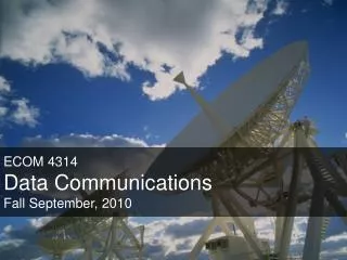
ECOM 4314 Data Communications Fall September, 2010. Chapter 7 Outline. Transmission Media GUIDED MEDIA UNGUIDED MEDIA. Transmission Media. Transmission media is any thing that can carry information from source to destination.

E N D
Chapter 7 Outline • Transmission Media • GUIDED MEDIA • UNGUIDED MEDIA Data Communication
Transmission Media • Transmission media is any thing that can carry information from source to destination. • Transmission media are located below the physical layer and controlled by physical layer. • Transmission media is usually free space, metallic cable, or fiber optic. Data Communication
Transmission Media Figure 7.1 Transmission medium and physical layer Data Communication
Transmission Media Figure 7.2 Classes of transmission media Data Communication
Guided media • Guided media, which are those that provide a conduit from one device to another, include twisted-pair cable, coaxial cable, and fiber-optic cable. • A signal traveling along any of these media is directed and contained by physical limits of the medium. Data Communication
Twisted-pair cable • It consists of two conductors each with its own plastic isolation. • One used to carry signal , other is ground reference. The receiver use difference between two. Figure 7.3 Twisted-pair cable Data Communication
Twisted-pair cable • If the two wires are parallel, the effect of unwanted signal is not the same in both wires, this results in a difference at the receiver. • By twisting the pairs, a balance is maintained. • For example, suppose one wire is close to noise and other is farther , in the next twist the reverse is true. • Twisting make both wire are equally affected by external influences. Data Communication
Twisted-pair cable type • Unshielded twisted-pair (UTP) • Shielded twisted-pair (STP) Figure 7.4 UTP and STP cables Data Communication
Table 7.1 Categories of unshielded twisted-pair cables Data Communication
Twisted-pair cable Figure 7.5 UTP connector Data Communication
Twisted-pair cable performance • With increasing frequency , the attenuation sharply increase. Data Communication
Coaxial cable • Coaxial cable carries signals of higher frequency ranges than those in twisted-pair. • Instead of having two wires, coax has central core conductor of solid wire enclosed in insulating sheath which in true encased in outer conductor of metal foil . Data Communication
Coaxial cable Figure 7.7 Coaxial cable Data Communication
Coaxial cable Table 7.2 Categories of coaxial cables Data Communication
Coaxial cable Figure 7.8 BNC connectors Data Communication
Coaxial cable Figure 7.9 Coaxial cable performance Data Communication
Optical Fiber • Light travels in straight line as long as it is moving through a single uniform substance. • If a ray of light traveling through one substance suddenly enters another substance of difference density, the ray change direction. Data Communication
Optical Fiber Figure 7.10 Fiber optics: Bending of light ray Data Communication
Optical Fiber Figure 7.11 Optical fiber Data Communication
Propagation modes Figure 7.12 Propagation modes Data Communication
Figure 7.13 Modes Data Communication
Optical Fiber Table 7.3 Fiber types Data Communication
Figure 7.14 Fiber construction Data Communication
Figure 7.15 Fiber-optic cable connectors Data Communication
Figure 7.16 Optical fiber performance Data Communication
Advantages/disadvantages • Advantages • Noise resistance • Less signal attenuation • Higher bandwidth • Disadvantages • Cost • Installation and maintenance • unidirectional light propagation. Data Communication
Unguided Media • Unguided media transport electromagnetic waves without using a physical conductor. • This type of communication is often referred to as wireless communication. Data Communication
Figure 7.17 Electromagnetic spectrum for wireless communication Data Communication
Earth Atmosphere • Troposphere • 30 miles from earth • Air • Cloud, wind, weather • Jet plane travel • Ionosphere • Between troposphere and space • Free electrically charged particles Data Communication
Figure 7.18 Propagation methods Data Communication
Ground propagation • Radio travels through the lowest portion of the atmosphere • VLF (in range of 3KHz – 10 KHz) • Low attenuation • Atmosphere noise (heat & electricity) • For long-range radio navigation • LF (in range of 30 KHz – 300 KHz) • For long-range radio navigation • Greater attenuation Data Communication
Sky propagation • Higher frequency radio waves radiate • upward into ionosphere where they reflect back to earth. • Allows greater distance with lower output power Data Communication
Line-of-sight propagation • Very high frequency signals transmitted in straight • lines from antenna to antenna. • Antenna must be directional Data Communication
Wireless transmission waves Figure 7.19 Wireless transmission waves Data Communication
Radio waves Radio waves are used for multicast communications, such as radio and television, and paging systems. They can penetrate through walls. Highly regulated. Use omni directional antennas Data Communication
Radio waves • Ranging from 3 KHz and 1 GHZ • Omnidirectional, waves propagated in • all directions • Sender and receiver must not be aligned • Propagate in sky mode • With low frequencies can penetrate walls • The radio wave band is relatively narrow Data Communication
Microwave • Ranges from 1 and 300 GHz • The can be narrowly focused • A pair of antenna can be aligned without • Characteristics • Line-of-sight • Repeaters are needed for long distances • High frequency cannot penetrate walls • Microwave band is relatively wide, therefore wider • subbands can be assigned, (higher data rate) Data Communication
Microwave Figure 7.21 Unidirectional antennas Data Communication
infrared • Ranges from 300 GHz to 400 GHz • Used for short range communication • High frequency • Cannot penetrate walls Data Communication
References • Ayman, Maliha, “Data Communication Lectures”, IUG. • BehrouzA. Forouzan , “Data Communications and Networking”, 4rdEdition, Chapter7, 2007 Data Communication
Thanks Data Communication