Download
1 / 74
810 likes | 1.12k Views
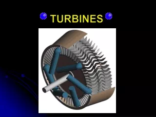
GAS TURBINES. PRESENTED BY: Er.VIKAS MONGA Lect. GPC, FEROZEPUR. INTRODUCTION.

E N D
GAS TURBINES PRESENTED BY: Er.VIKAS MONGA Lect. GPC, FEROZEPUR
INTRODUCTION A gas turbine is a machine delivering mechanical power or thrust. It does this using a gaseous working fluid. The mechanical power generated can be used by, for example, an industrial device. The outgoing gaseous fluid can be used to generate thrust. In the gas turbine, there is a continuous flow of the working fluid.
Cont… This working fluid is initially compressed in the compressor. It is then heated in the combustion chamber. Finally, it goes through the turbine. The turbine converts the energy of the gas into mechanical work. Part of this work is used to drive the compressor. The remaining part is known as the net work of the gas turbine.
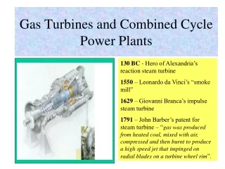
History of gas turbines We can distinguish two important types of gas turbines. There are industrial gas turbines and there are jet engine gas turbines. Industrial gas turbines were developed rather slowly. This was because, to use a gas turbine, a high initial compression is necessary. This rather troubled early engineers. Due to this, the first working gas turbine was only made in 1905 by the Frenchman Rateau.
Cont. The first gas turbine for power generation became operational in 1939 in Switzerland. It was developed by the company Brown Boveri. Gas turbines had a rather low thermal efficiency. But they were still useful. This was because they could start up rather quickly. They were therefore used to provide power at peak loads in the electricity network. In the 1980’s, natural gas made its breakthrough as fuel. Since then, gas turbines have increased in popularity. After world war 2, the gas turbine developed rapidly.
Cont… New high-temperature materials, new cooling techniques and research in aerodynamics strongly improved the efficiency of the jet engine. It therefore soon became the primary choice for many applications. Currently, there are several companies producing gas turbines. The biggest producer of both industrial gas turbines and jet engines is General Electric (GE) from the USA. Rolls Royce and Pratt & Whitney are also important manufacturers of jet engines.
Cont… The cycle that is present is known as the Joule-Brayton cycle. This cycle consists of four important points. We start at position 1where the gas has passed through the inlet, after that the gas then passes through the compressor. We assume that the compression is performed isentropically. So, s1 = s2. The gas is then heated in the combustor. (Point 3.) This is done isobarically (at constant pressure). So, p2 = p3. Finally, the gas is expanded in the turbine. (Point 4.) This is again done isentropic ally. So, s3 = s4.
Cont… The whole process is visualized in the temperature-entropy diagram as shown above. The cycle consists of an isentropic compression of the gas from state 1 to state 2; a constant pressure heat addition to state 3; an isentropic expansion to state 4, in which work is done; and an isobaric closure of the cycle back to state 1. Above Figure shows, a compressor is connected to a turbine by a rotating shaft. The shaft transmits the power necessary to drive the compressor and delivers the balance to a power-utilizing load, such as an electrical generator.
Cont… When examining the gas turbine cycle, we do make a few assumptions. We assume that the working fluid is a perfect gas with constant specific heats cp and cv. Also, the specific heat ratio k (sometimes also denoted by ) is constant. We also assume that the kinetic/potential energy of the working fluid does not vary along the gas turbine. Finally, pressure losses, mechanical losses and other kinds of losses are ignored.
Classification The gas turbine can be classified into two categories, i.e. impulse gas turbine and reaction gas turbine. If the entire pressure drop of the turbine occurs across the fixed blades, the design is impulse type, while if the drop is taken place in the moving blades, the fixed blades serving only as deflectors, the design is called reaction type.
Cont… The advantage of the impulse design is that there is no pressure force tending to move the wheel in the axial direction and no special thrust balancing arrangement is required. There being no tendency for gas to leak over the tips of the moving blades. A purely reaction turbine is not generally used. In a small multi-stage construction the velocity change in the moving and fixed blades is about the same, the design being 50% reaction types.
GAS TURBINE POWER PLANT The simple gas turbine power plant mainly consists of a gas turbine coupled to a rotary type air compressor and a combustor or combustion chamber which is placed between the compressor and turbine in the fuel circuit. Auxillaries, such as cooling fan, water pumps, etc. and the generator itself, are also driven by the turbine. Other auxillaries are starting device, lubrication system, duct system, etc. A modified plant may have in addition to the above, an inter-cooler, a regenerator and a reheater. The arrangement of a simple gas turbine power plant is shown in Figure in next slide
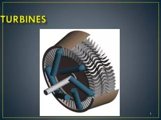
Construction The basic construction of a gas turbine employs vanes or blades mounted on a shaft and enclosed in a casing. The flow of fluid through turbine in most designs is axial and tangential to the rotor at a nearly constant or increasing radius. There are two types of blades used in all turbines : those that are fixed on the rotor and move with the shaft and those that are fixed to the casing and help to guide and accelerate or decelerate the flow of fluid, being called fixed blades or vanes.
Cont… The power of the turbine depends upon the size, shape and the speed of the blades used. Multi-staging is employed to increase the power output of the turbine by placing additional sets of fixed and moving blades in series. To prevent leakage of gas along the shaft gas seals or glands are provided where the shaft emerges from the turbine casing. The extending lengths of the shaft on the two sides of the turbine are supported on journal bearings which also maintain it’s proper alignment.
Accessories There are several accessories fitted to the turbine. These are : a tachometer driven through a gear box, an over speed governor, a lubricating oil pump and a fuel regulator. The starting gear is mounted on the shaft at one end. The tachometer shows the speed of the machine and also actuates the fuel regulator in case of speed rises above or fall below the regulated speed, so that the fuel regulator admits less fuel or more fuel into the combustor and varies the turbine power according to demand of load.
Cont… The governor back off fuel feed, if the exhaust temperature from turbine exceeds the safe limit, thermal switches at the turbine exhaust acting on fuel control to maintain present maximum temperature. The lubricating pump supplies oil to bearing under pressure. Other auxillaries used on the turbine plant include the starting motor or engine with starting gear, oil coolers, filters and inlet and exhaust mufflers. The turbine (and with it the compressors) is driven by the starting motor through a clutch and set-up gearing. A standby motor driven pump is also provided for emergency service. A failure of lubricating pump system results in stopping of the unit automatically.
Compressor A compressor is a device that is used to supply compressed air to the combustion chamber. Compressors are broadly classified as positive displacement type and rotodynamic type and may be of single stage or multi-stage design. In the positive displacement machine, successive volumes of air are pressurized within a closed space. These may be of reciprocating type or rotary type. In reciprocating type machines, air is compressed by a piston in a cylinder, while in the rotary type, this is accomplished by positive action of rotating elements.
Cont… The roto-dynamic compressors may be of radial flow, axial flow or mixed flow type. In these machines, compression takes place by dynamic action of rotating vanes or impellers which impart velocity and pressure to the air as it flows through the compressor. Roto-dynamic type compressors include the centrifugal, axial and mixed flow compressors which are all high speed machines running at as high as 3,000 to 4,000 RPM driven by turbines. These are designed to have high value of air discharge capacity at moderate pressure. These types of compressors are usually employed for gas turbine applications.
Combustor A combustor is a device inside which the combustion of fuel takes place. For an efficient operation of gas turbine plant, it is necessary to ensure good combustor performance. A good combustor should achieve completeness of fuel combustion and the lowest possible pressure drop in the gas, besides being compact, reliable and easy to control. Complete combustion of fuel depends upon three factors, viz. temperature, time and turbulence. Temperature in the combustor directly affects combustion and high temperature is conductive to rapid combustion.
Generator It is a device that generates electricity. It is coupled to the same shaft of turbine and runs at same speed to that of the turbine. The capacity of generators depends on installed capacity of the plant. The types of generators to be used depend on the purpose for which electrical energy is to be produced.
TYPES OF GAS TURBINE POWER PLANTS The gas turbine power plants can be classified mainly into two categories. These are :open cycle gas turbine power plant and closed cycle gas turbine power plant. Open Cycle Gas Turbine Power Plant In this type of plant the atmospheric air is charged into the combustor through a compressor and the exhaust of the turbine also discharge to the atmosphere. Closed Cycle Gas Turbine Power Plant In this type of power plant, the mass of air is constant or another suitable gas used as working medium, circulates through the cycle over and over again.
OPEN CYCLE GAS TURBINE POWER PLANTAND ITS CHARACTERISTICS The schematic arrangement of a simple open cycle gas turbine power plant is shown in Figure in next slide
Cont… In the process shown the cycles are : 2-3: Isentropic compression 3-4: Heat addition at constant pressure 4-1: Isentropic expansion 1-2: Heat rejection at constant pressure The ideal thermal efficiency for the cycle,ç t, is given by, Heat supplied - Heat rejected/Heat supplied where, r is the compression ratio=V2/V3and k is the ratio of specific heat of the gas.
Cont… In actual operation the processes along 2-3 and 4-1 are never isentropic and the degree of irreversibility of these processes and the mechanical efficiencies of the machine components greatly reduce the ideal value of thermal efficiencies of the cycle. If the air entering the combustor is preheated by the heat of exhaust gases escaping from the turbine, some heat can be recovered resulting into an increase in the efficiency of the cycle improved. Such heating of combustion air is known as regeneration and the heat exchanger transferring heat from gas to air is called regenerator.
Cont… Since most of the output of turbine is consumed by the compressor, the actual efficiency of the cycle greatly depends upon an efficient working of the compressor. To attain higher compression ratios, it is necessary to use multi-stage compression with inter-cooling. In actual practice, all these modifications, viz. regeneration, reheating and inter-cooling are combined in a simple modified cycle and a substantial gain in the overall plant efficiency is attained.
5 CLOSED CYCLE GAS TURBINE POWER PLANTAND ITS CHARACTERISTICS In the closed cycle, quantity of air is constant, or another suitable gas used as working medium, circulates through the cycle over and over again. Combustion products do not come in contact with the working fluid and, thus, remain closed.
Cont… A development in the basic gas turbine cycle is the use of the closed cycle which permits a great deal of flexibility in the use of fuels. Moreover, working medium of the plant could be any suitable substance other than air which would give higher efficiency. An arrangement of closed gas turbine cycle is shown in Figure in next slide. In this cycle, working fluid is compressed through the requisite pressure ratio in the compressor, and fed into the heater, where it is heated up to the temperature of turbine itself.
CONT… The fluid is then expanded in the turbine and the exhaust is cooled to the original temperature in the pre-cooler. It then re-enter the compressor to begin the next cycle. Thus, the same working fluid circulates through the working parts of the system. The heater burns any suitable fuel and provides the heat for heating the working fluid. In fact, this combustor is akin to an ordinary boiler furnace, working at the atmosphere pressure and discharging the gaseous products to the atmosphere. There is, thus, a great deal of flexibility in respect of furnace design and use of fuel, allowing low cost fuel to be used.
Cont… Another advantages in use of closed cycle is the choice of selecting a convenient pressure range, once the pressure ratio has been selected. The volume of the air or the working fluid in the cycle depends upon the pressure range which, in turn, affects the sizes of the air heater, compressor, turbine, etc. In a closed cycle, there is no restriction to keep the pressure low and this could be kept at any suitable value say 7.03 kg/cm2(68.9 N/cm ) abs.
Cont… The pre-cooler in a closed cycle plant is an important equipment and corresponds to the condenser of a steam plant. However, unlike the condenser, cooling water in the pre-cooler could be heated to a fairly high temperature depending upon temperature of exit gas from the turbine, and then used elsewhere in the plant. The design of pre-cooler is commonly of the shell and tube type, and water is the coolant commonly used. The air heater of the closed cycle corresponds to the water heaters of the steam plant, but with one important difference that it has very small heat storage capacity .
FUEL FOR GAS TURBNE POWER PLANTS Natural gas is the ideal fuel for gas turbines, but this is not available everywhere. Blast furnace and producer gas may also be used for these plants. However, liquid fuels of petroleum origin, such as, distillate oils or residual oils are most commonly used for gas turbine power plants. The essential qualities of these fuels include proper volatility, viscosity and calorific value. At the same time, the fuel should be free from any content of moisture and suspended impurities that may clog the small passages of the nozzles and damage valves and plungers of the fuel pump.
Cont… However, liquid fuels of petroleum origin, such distillate oils or residual oils are most commonly used for gas turbine plants. Residual oils burns with less ease than distillate oils and the heaters are often used to start the unit from cold, after which the residual oils are red into the combustor. Pre-heating of residual oils may be necessary in cold climates. Use of solid fuel, such as coal in pulverized form in gas turbines presents several difficulties, most of which have been only partially overcome.
Types of Gas Turbines • Jet engines Airbreathing jet engines are gas turbines optimized to produce thrust from the exhaust gases, or from ducted fans connected to the gas turbines. Jet engines that produce thrust from the direct impulse of exhaust gases are often called turbojets, whereas those that generate thrust with the addition of a ducted fan are often called turbofans or (rarely) fan-jets. Gas turbines are also used in many liquid propellant rockets, the gas turbines are used to power a turbopump to permit the use of lightweight, low pressure tanks, which saves considerable dry mass.
Turboprop engines A turboprop engine is a type of turbine engine which drives an external aircraft propeller using a reduction gear. Turboprop engines are generally used on small subsonic aircraft, but some large military and civil aircraft, such as the Airbus A400M, Lockheed L-188 Electra and Tupolev Tu-95, have also used turboprop power.
Aeroderivative gas turbines Aeroderivatives are also used in electrical power generation due to their ability to be shut down, and handle load changes more quickly than industrial machines. They are also used in the marine industry to reduce weight. The General Electric LM2500, General Electric LM6000, Rolls-Royce RB211 and Rolls-Royce Avon are common models of this type of machine.
Amateur gas turbines • In its most straightforward form, these are commercial turbines acquired through military surplus or scrapyard sales, then operated for display as part of the hobby of engine collecting. In its most extreme form, amateurs have even rebuilt engines beyond professional repair and then used them to compete for the Land Speed Record
Auxiliary power units APUs are small gas turbines designed to supply auxiliary power to larger, mobile, machines such as an aircraft. They supply: • compressed air for air conditioning and ventilation, • compressed air start-up power for larger jet engines, • mechanical (shaft) power to a gearbox to drive shafted accessories or to start large jet engines, and • electrical, hydraulic and other power-transmission sources to consuming devices remote from the APU.
Industrial gas turbines for power generation Industrial gas turbines differ from aeronautical designs in that the frames, bearings, and blading are of heavier construction. They are also much more closely integrated with the devices they power—electric generator—and the secondary-energy equipment that is used to recover residual energy (largely heat). They range in size from man-portable mobile plants to enormous, complex systems weighing more than a hundred tonnes housed in block-sized buildings.
Turboshaft engines Turboshaft engines are often used to drive compression trains (for example in gas pumping stations or natural gas liquefaction plants) and are used to power almost all modern helicopters. The primary shaft bears the compressor and the high speed turbine (often referred to as the Gas Generator), while a second shaft bears the low-speed turbine (a power turbine or free-wheeling turbine on helicopters, especially, because the gas generator turbine spins separately from the power turbine).
Microturbines Microturbines are one of the most promising technologies for powering hybrid electric vehicles. They range from hand held units producing less than a kilowatt, to commercial sized systems that produce tens or hundreds of kilowatts. Basic principles of microturbine are based on micro combustion.
Cont… Microturbine systems have many claimed advantages over reciprocating engine generators, such as higher power-to-weight ratio, low emissions and few, or just one, moving part. Nevertheless reciprocating engines overall are still cheaper when all factors are considered. Microturbines also have a further advantage of having the majority of the waste heat contained in the relatively high temperature exhaust making it simpler to capture, whereas the waste heat of reciprocating engines is split between its exhaust and cooling system.
External combustion Most gas turbines are internal combustion engines but it is also possible to manufacture an external combustion gas turbine which is, effectively, a turbine version of a hot air engine. Those systems are usually indicated as EFGT (Externally Fired Gas Turbine) or IFGT (Indirectly Fired Gas Turbine). External combustion has been used for the purpose of using pulverized coal or finely ground biomass (such as sawdust) as a fuel.
Gas turbines in surface vehicles Gas turbines are often used on ships, locomotives, helicopters, tanks, and to a lesser extent, on cars, buses, and motorcycles. Gas turbines offer a high-powered engine in a very small and light package. However, they are not as responsive and efficient as small piston engines over the wide range of RPMs and powers needed in vehicle applications. Turbines have historically been more expensive to produce than piston engines, though this is partly because piston engines have been mass-produced in huge quantities for decades, while small gas turbine engines are rarities; however, turbines are mass-produced in the closely related form of the turbocharger.
Turbocharger The turbocharger is basically a compact and simple free shaft radial gas turbine which is driven by the piston engine's exhaust gas. The centripetal turbine wheel drives a centrifugal compressor wheel through a common rotating shaft. This wheel supercharges the engine air intake to a degree that can be controlled by means of a wastegate or by dynamically modifying the turbine housing's geometry (as in a VGT turbocharger). It mainly serves as a power recovery device which converts a great deal of otherwise wasted thermal and kinetic energy into engine boost.
Concept cars The first serious investigation of using a gas turbine in cars was in 1946 when two engineers, Robert Kafka and Robert Engerstein of Carney Associates, a New York engineering firm, came up with the concept where a unique compact turbine engine design would provide power for a rear wheel drive car. The original General Motors Firebird was a series of concept cars developed for the 1953, 1956 and 1959 Motorama auto shows, powered by gas turbines. Toyota demonstrated several gas turbine powered concept cars such as the Century gas turbine hybrid in 1975, the Sports 800 Gas Turbine Hybrid in 1979 and the GTV in 1985.