Download
1 / 16
160 likes | 376 Views
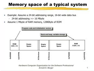
Memory space of a typical system. Example: Assume a 24-bit addressing range, 16-bit wide data bus 24-bit addressing >> 16 Mbyte Assume 1 Mbyte of RAM memory, 128KByte of ROM. Program code and initialization vectors. Stack and heap, variable storage. RAM 512K x 16. ROM 64K x 16. Empty

E N D
Memory space of a typical system • Example: Assume a 24-bit addressing range, 16-bit wide data bus • 24-bit addressing >> 16 Mbyte • Assume 1 Mbyte of RAM memory, 128KByte of ROM Program code and initialization vectors Stack and heap, variable storage RAM 512K x 16 ROM 64K x 16 Empty Space Empty Space Empty Space 0xF00000 0x000000 0x01FFFE 0xFFFFFE IO Devices IO Devices Hardware Computer Organization for the Software Professional Arnold S. Berger
Byte Packing 000000 000004 FFFFF4 000010 FFFFF8 FFFFF0 00000C FFFFFC 000008 Byte 2 – Address 000006 Byte 3 – Address 000003 Byte 2 – Address 000002 Byte 1 – Address 000005 Byte 0 – Address 000004 Byte 3 – Address 000007 Byte 3 – Address 000013 Byte 0 – Address 000008 Byte 3 – Address 00000F Byte 2 – Address 00000A Byte 1 – Address 00000D Byte 0 – Address 00000C Byte 0 – Address 000000 Byte 2 – Address 00000E Byte 2 – Address FFFFFE Byte 1 – Address 000009 Byte 3 – Address 00000B Byte 1 – Address 000001 Byte 0 – Address FFFFF8 Byte 1 – Address 000011 Byte 3 – Address FFFFFB Byte 1 – Address FFFFF1 Byte 3 – Address FFFFFF Byte 0 – Address FFFFF0 Byte 3 – Address FFFFF3 Byte 2 – Address FFFFF2 Byte 0 – Address FFFFFC Byte 0 – Address 000010 Byte 1 – Address FFFFF5 Byte 3 – Address FFFFF7 Byte 2 – Address FFFFF6 Byte 2 – Address FFFFFA Byte 1 – Address FFFFF9 Byte 1 – Address FFFFFD Byte 2 – Address 000012 Byte 0 – Address FFFFF4 Word Address Hardware Computer Organization for the Software Professional Arnold S. Berger
Memory organization (2) • Memory organization usually depends upon the width of the processor data bus • The 68000 is a 32-bit processor internally, but interfaces to a 16-bit data bus • All addresses are 32-bits internally, with 24-bits external (16M) Bit Bit Bit 7 0 15 8 7 0 15 8 7 0 0x0000 0x00000 0x000001 0x00001 0x000000 S T S S T Byte Addressable memory for a 16-bit processor with a 20-bit addressing range Intel 80186 Little Endian Byte Addressable memory for a 16-bit processor with a 24-bit addressing range MC68000 Big Endian Byte Addressable memory for an 8-bit processor with a 16-bit addressing range T I R R I R G N G N I N G 0xFFFE 0xFFFFE 0xFFFFFF 0xFFFFF 0xFFFFFE 0xFFFF Hardware Computer Organization for the Software Professional Arnold S. Berger
Memory organization • In byte-addressable systems, low-order address bits do the byte addressing • Example: The 68000 has 23 external address lines and can address 224 bytes ( 0..16,777,215 ) or 223 words ( 0..8,388,607 ) • Address bit A0 is implied by two other signals, UDS and LDS • Can be considered to be the byte selector bits for a word addressing system, A1..A23 • For a 32-bit addressing system and a 32-bit data path ( long word ) address bits A2..A31 ( 0..1,073,741,823 ) address the word and address bits A0,A1 address the byte of the word 8 7 0 8 7 15 0 23 16 23 16 24 31 15 24 31 A0 1 0 1 0 A1 1 1 0 0 A0 0 1 0 1 A1 0 0 1 1 Little Endian Big Endian Hardware Computer Organization for the Software Professional Arnold S. Berger
68000 Memory Access 0xFFFFFC 0xFFFFFE 0x000000 0x000002 D15 D8 D7 68000 Processor D0 0x000003 0x000001 Note: A word access on a byte boundary would require two memory operations to complete and is not allowed in the 68000 processor. 0xFFFFFF 0xFFFFFD Byte Access A0=0: LDS=1, UDS=0 A0=1: UDS=1, LDS=0 Word Access A0=0: LDS=0, UDS=0 A0=1: LDS=1, UDS=1 A1..A23 Lower Data Strobe (LDS) Upper Data Strobe (UDS) Hardware Computer Organization for the Software Professional Arnold S. Berger
Memory organization (4) • Storing 32-bit values in a 16-bit external memory EVEN BYTE ODD BYTE 7 6 5 4 2 1 0 7 6 5 4 3 2 1 0 1 LONG WORD = 32 BITS 15 14 13 12 11 10 9 8 7 6 5 4 3 2 1 0 MSB HIGH ORDER WORD LONG WORD 0 LOW ORDER WORD LSB MSB LONG WORD 1 LSB MSB LONG WORD 2 LSB Hardware Computer Organization for the Software Professional Arnold S. Berger
Introduction to Assembly Language • Every computer system has a fundamental set of operations that it can perform • These operations are defined by the instruction set of the processor • The instruction set is the atomic element of the processor • All the complex operations are achieved by building sequences of these fundamental operations • Assembly language is the human readable form of these instructions, called machine language Instead of writing a program in machine language as: 00000412 307B7048 00000416 327B704A 0000041A 1080 0000041C B010 000041E 67000008 00000422 1600 00000424 61000066 00000428 5248 0000042A B0C9 We write the program in assembly language as: MOVEA.W (TEST_S,PC,D7),A0 *We'll use address indirect MOVEA.W (TEST_E,PC,D7),A1 *Get the end address MOVE.B D0,(A0) *Write the byte CMP.B (A0),D0 *Test it BEQ NEXT_LOCATION *OK, keep going MOVE.B D0,D3 *copy bad data BSR ERROR *Bad byte ADDQ.W #01,A0 *increment the address CMPA.W A1,A0 *are we done? Hardware Computer Organization for the Software Professional Arnold S. Berger
Using labels TEST_LOOP MOVE.B (A2),D6 *Let D6 test the patterns for done CMPI.B #END_TEST,D6 *Are we done? BEQ DONE *We've done the 4 patterns LEA ST_ADDR,A0 *Set up the starting address in A0 LEA END_ADDR,A1 *Set up the ending address in A1 JSR DO_TEST *Go to the test ADDA.W #01,A2 *Point to the next test pattern BRA TEST_LOOP *Go back to the next location DONE STOP #EXIT *Test is over, stop • Label, a symbolic name given to a variable or a constant • Usually refers to a memory address • Must be defined in column 1 • Labels make the program readable • A program may be written without labels, but almost no one ever does it • Labels allow the assembler program to automatically calculate addresses • Avoids errors in addressing • Example, consider the following snippet of code: • Question: What does this instruction do? foo BRA foo *Huh? Hardware Computer Organization for the Software Professional Arnold S. Berger
Hardware Organization of the MC68000 Holds address of the next instruction to be executed If necessary Holds the address of memory reads/writes Program Counter (PC) 32 Effective Address Register (EAR) 32 External Bus Memory and I/O Interface Control Pipeline Internal Bus Instruction Register(IR) 16 Instruction Decode and Control General Registers D0..D7 A0..A6 A7= User Stack pointer (USP) A7’=Supervisor Stack Pointer(SSP) Holds first word of currently executing instruction Temporary Register 32 32 Holds operands or intermediate results Performs all logical or arithmetic operations ( ADD, SHIFT, etc. ) Arithmetic and Logic Unit (ALU) 8 CCR SR Holds result of ALU Operations 32 Hardware Computer Organization for the Software Professional Arnold S. Berger
Programmer’s model of an MC68000 MSB LSB MSB LSB 31 16,15 0 31 8,7 16,15 0 A7 (USP) D0 D1 USER STACK POINTER D2 31 0 DATA REGISTERS D3 PC D4 D5 PROGRAM COUNTER D6 0 7 D7 CCR 31 16,15 LSB 0 MSB CONDITION CODE REGISTER A0 A1 31 16,15 0 A2 A3 ADDRESS REGISTERS A7’ (SSP) A4 SUPERVISOR STACK POINTER A5 15 0 8,7 A6 CCR SR STATUS REGISTER Hardware Computer Organization for the Software Professional Arnold S. Berger
CCR Register • The Condition Code Register, or CCR register, contains a set of 5 condition bits • Bits change constantly with the result of each instruction • X BIT: Extend bit- Used with multi-precision arithmetic • N BIT: Negative bit- Indicates that the result is a negative number • Z BIT: Zero bit: Indicates that the result is equal to zero • V BIT: Overflow: Indicates that the result may have exceeded the range of the operand • C BIT: Carry bit: Indicates that a carry was generated in a mathematical operation DB7 DB6 DB5 DB4 DB3 DB2 DB1 DB0 X N Z V C CCR Hardware Computer Organization for the Software Professional Arnold S. Berger
Effective Address MOVE.W dst EA src EA 15 12 11 6 5 0 • The effective address, EA, determines how the operands of an instruction are to be accessed by the processor • The kinds of EA’s are the addressing modes of the architecture • Consider the form of the opcode word shown below: • MOVE.W instruction: Move the word contents of the memory location specified by the src EA to the memory location specified by the dst EA • This information is encoded in the 16 bits of the op code word • OPCODE/SIZE = DB12-DB15 ( MOVE.W) • Source Effective Address = DB0-DB5 • Destination Effective Address = DB6-DB11 • May have to retrieve additional words from memory to complete the instruction • Note: Not all instructions have the same form as the MOVE instruction Hardware Computer Organization for the Software Professional Arnold S. Berger
Instruction format in memory • Example: an immediate operand is the actual data value • Generally represented as OP CODE #DATA • Example: start MOVE.W #$0A55,D0 *Initialize D0 EVEN BYTE ODD BYTE 7 6 5 4 2 1 0 7 6 5 4 3 2 1 0 15 14 13 12 11 10 9 8 7 6 5 4 3 2 1 0 • It is a MOVE.W instruction • The source operand is immediate data • The destination operand is register D0 OP CODE WORD FIRST WORD SPECIFIES OPERATIONS AND MODES IMMEDIATE OPERAND IF ANY, ONE OR TWO WORDS • The immediate data value, $0A55 SOURCE EFFECTIVE ADDRESS EXTENSION IF ANY, ONE OR TWO WORDS DESTINATION EFFECTIVE ADDRESS EXTENSION Not used IF ANY, ONE OR TWO WORDS Hardware Computer Organization for the Software Professional Arnold S. Berger
Instruction format in memory(2) • Example 2: Absolute operands exactly specify the locations of the data • Generally represented as: OP CODE source address,dest address • Example: MOVE.W $0A550000,$1000BB00 EVEN BYTE ODD BYTE 7 6 5 4 2 1 0 7 6 5 4 3 2 1 0 15 14 13 12 11 10 9 8 7 6 5 4 3 2 1 0 • It is a MOVE.W instruction • The source operand is absolute address • The destination operand is absolute • address OP CODE WORD FIRST WORD SPECIFIES OPERATIONS AND MODES SOURCE EFFECTIVE ADDRESS HIGH ORDER WORD SOURCE EFFECTIVE ADDRESS LOW ORDER WORD • $0A55 DESTINATION EFFECTIVE ADDRESS HIGH ORDER WORD • $0000 • $1000 DESTINATION EFFECTIVE ADDRESS LOW ORDER WORD • $BB00 Hardware Computer Organization for the Software Professional Arnold S. Berger
Word Alignment • It is best to try to align memory accesses on natural boundaries • Some processors (X86) will allow accesses to occur for non-aligned words • Requires multiple memory accesses to input data • MC68000 processor does not allow non-aligned accesses • Will generate an exception trap and an error routine will need to be called to recover • Trying to address a word beginning at address 1 will cause a non-aligned access to occur Low order byte 1 0 3 2 High order byte Hardware Computer Organization for the Software Professional Arnold S. Berger
Flow charting (3) Set up environment TEST = FALSE Keyboard Input Run Self-tests TEST = TRUE Interpret keystroke Scan key board 8 Hardware Computer Organization for the Software Professional Arnold S. Berger