
FSRUG
E N D
Presentation Transcript
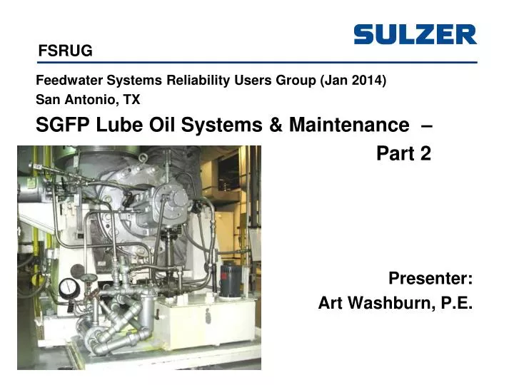
FSRUG Feedwater Systems Reliability Users Group (Jan 2014) San Antonio, TX SGFP Lube Oil Systems & Maintenance – Part 2 Presenter: Art Washburn, P.E.
FSRUG DISCUSSION POINTS • Two Rules to Get You Home and Plant Priorities • Lubrication Oil Systems – Types • Lubrication System – Static Sump • Lubrication System – Forced Feed • Grease and Oil Mist Injection • Oil Ring Submergence • Oil Ring Journal Surface Peripheral Velocity Limit • Oil Ring – Maintenance • Lubrication System – Forced Feed • Forced Feed – Drain Piping • Forced Feed System – Challenges • Water Intrusion – Traditional Oil Deflector vs. INPRO Deflector • Industry Events • Source References
FSRUG Two Rules:
FSRUG Two Rules: Rule #1 – Make Conservative Decisions
FSRUG Two Rules: Rule #1 – Make Conservative Decisions Rule #2 – Maintain Design Control
FSRUG Two Rules: Rule #1 – Make Conservative Decisions Rule #2 – Maintain Design Control Plant Priorities:
FSRUG Two Rules: Rule #1 – Make Conservative Decisions Rule #2 – Maintain Design Control Plant Priorities: • Nuclear Safety
FSRUG Two Rules: Rule #1 – Make Conservative Decisions Rule #2 – Maintain Design Control Plant Priorities: • Nuclear Safety • Legal Requirements
FSRUG Two Rules: Rule #1 – Make Conservative Decisions Rule #2 – Maintain Design Control Plant Priorities: • Nuclear Safety • Legal Requirements • Efficiency
FSRUG Lubrication System – Static Sump
FSRUG Lubrication System – Static Sump • Bearing Housing contains oil as a static sump • API-610: Oil Rings (and flingers) used to deliver oil (GPM) to the bearings shall have an operating submergence of 0.12" or 0.25" above the lower edge of the bore of an oil ring. • Flingers are positively attached secured to the shaft. • Oil is lifted by oil ring to shaft and flows to bearing • Oil can be lifted by oil ring and flows to an internal cast trough in bearing housing and flows to bearing • Heat Sink: Oil Cooler located in bottom of sump in the oil or cast in the Bearing Housing. Pumpage or separate closed cooling water system.
FSRUG Oil Ring Submergence Particulate in Oil? • Stability issues identified in the 1990s. Testing identified oil rings can go unstable and bounce around. Mechanical contact inside the bearing housing would nick off pieces of oil ring (non-ferrous, silicon bronze). Particulate in oil (non-ferrous). • Increased submergence improved stability of oil rings and oil delivery (GPM). • The multitude of pumps in the Field operate satisfactory. • Look for particulate (oil ring material) from oil sampling.
FSRUG Oil Ring Submergence Particulate in Oil? Drive End or Thrust End • Design for Between Bearing Pump: • Oil Rings – Same size (minimizes risk on installing in wrong location) • Oil Submergence in both bearing housings (same oil level) • Oil Ring Submergence – different on each end • Reason: Journal surface for oil ring can be different – • Drive End shaft diameter can be larger to transmit torque • Submergence may be more shallow on drive end • Look for oil ring particulate on drive end. • Solution: If particulate present, then Increase submergence
FSRUG Oil Ring Journal Surface Peripheral Velocity Limit Oil Ring Rides on a Journal Surface • Journal Surface Peripheral Velocity Limit, 45 to 59 fps • Peripheral Velocity = [π x D/12] x RPM/60, in fps (FT/Sec) • At 45 fps, Slip commences between the oil ring and journal surface and degrades delivery of oil (GPM) • At 59 fps slip continues to degrade delivery of oil (GPM), until a Force Feed Lubrication System would be required.
FSRUG Oil Ring - Maintenance Consider Oil Ring as a consumable item • Replace Oil Ring when bearing housing is disassembled • Oil Ring can wear over time and affect performance (delivery of oil)
FSRUG Oil Ring – Example of Damage
FSRUG Oil Ring – Example of Damage
FSRUG Oil Ring – Example of Damage
FSRUG Forced Feed Lubrication System Typical Schematic
FSRUG Forced Feed Lubrication System Pressure Setting Logic:
FSRUG Forced Feed Lubrication System Bearing Housing Assemblies w/Oil Pump
FSRUG Forced Feed Lubrication System Reservoir Layout
FSRUG Forced Feed Lubrication System • Separate Ancilliary System to Main Pump includes: • Reservoir (suction source) • Oil Pumps: • Shaft Driven off main pump Thrust Bearing Housing (and coupled) • Auxiliary pump (electric AC, optional DC) mounted vertically on top of Reservoir • Pressure regulator (relief valve) for both oil pumps in Reservoir • Lube oil supply piping with oil cooler, filter (duplex) • Reverse Rotation Protection for the Shaft Driven Oil Pump
FSRUG Forced Feed Lubrication System Continued: • Supply Tubing Feeds Bearings (e.g., Drive End Bearing, Non-Drive Thrust End Bearing) • Supply Oil flow to each bearing (GPM) is metered by an orifice to each bearing (Typical Example): • Journal Bearing (Orifice 0.093" Dia, Pressure 12 PSIG, Flow 0.6 GPM x 2 bearings) • Tilt Pad Trust Bearing (Orifice x" Dia, Pressure 12 PSIG, Flow 1.12 GPM per Side – Active and Inactive) • Leakoff through relief valve • Total Capacity: 3.44 GPM Plus leakoff • Option to Feed Driver (Motor) Bearings
FSRUG Forced Feed Lubrication System Standard Rule for Supplying Forced Feed Lube System: • Electric Driver (motor) – Pump Supplier provides Lube System • Turbine Driver – Turbine Supplier provides Lube System • Ball Radial / Ball Thrust Bearing Arrangement can be Lubricated by Static Sump or Pressure Lube • Sleeve Radial / Ball Thrust Bearing Arrangement can be Lubricated by Static Sump or Pressure Lube • Tilt Pad Type Thrust Bearing Arrangement requires Pressure Lube
FSRUG Forced Feed – Drain Piping • Gravity Drains from bearing housing(s) to reservoir • Bearing Housings must be well vented • Drain line designed to be half full to assure vented from bearing housing back to reservoir • Hard Pipe (not flex hose) • Drain line sloped: Example, 2" Schedule 80 Pipe • 0.25"/FT Slope (4.28 GPM) • 0.50"/FT Slope (8.56 GPM) • Reservoir Level (Normal Operation) – below drain line [Maintain design required level with a range]
FSRUG Forced Feed – Drain Piping
FSRUG Forced Feed – Reservoir Level Above Drain Piping
FSRUG Forced Feed – Bearing Housings to be Well Vented
FSRUG Forced Feed – Bearing Housings to be Well Vented
FSRUG Forced Feed – Drain Header Vertical Piping Replaced with Metallic Flex Hoses/Fittings (likely Choking the drainage)
FSRUG Forced Feed – Drain Piping for Motor Driven Assy
FSRUG Forced Feed – Drain Piping for Turbine Driven Assy
FSRUG Forced Feed System – Challenges • Replacement Relief Valve • (Obsolesence) – Minor Mounting Changes • Results in re-plumbing reservoir internals
FSRUG Forced Feed System – Challenges Changes in Supply Oil Pressure • to improve heat sink with increased flow • potential impact to pressure switch setpoints • potentially impacts maximum capacity of pump to supply oil to bearings and relief valve. • Supply Orifice is integral to bearing housing • One plant added orifice outside of bearing housing. Now have 2 orifices in series. Now required to run lube oil supply pressure at 24 psig to deliver the required oil.
FSRUG Forced Feed System – Challenges • Original lube oil pumps were designed for Clock-Wise (CW) Rotation. Pumps are gear type positive displacement. The thrust plate is installed on the pump to handle thrust from "CW" rotation. • Original pumps were allowed to operate Counter-Clock-Wise (CCW) rotation; however, thrust plate was never installed on the opposite end of the pump for thrust. The CCW pump thrust condition was accepted as long as pump differential pressure was limited to 24 psig (max).
FSRUG Industry Events: • 1989 - Plant Turbine Trip with Loss of Lubrication Oil for Turbine, Generator and Excitor Bearings. • Causes: • Backup AC and DC Oil Pumps were not periodically tested to assure function • DC Backup Oil Pump tripped from protective relay (not sized properly) • Reliability Issues for System • Cause: Excessive moisture in oil. • Water in Oil – 3 Types: Free Water, Emulsified, Relative Humidity • Most common Water Separation System: Bowser (WWII Technology) – branch side stream oil and enter a sudden enlargement; slows velocity down and allows free water and some emulsified water to separate. • Bowser Type System replaced with Coalescing Filters: Removes the 3 types of water present in the system. Improves system reliability and shortens outages for startup.
FSRUG Industry Events: • 2011 - Plant Turbine Trip with Loss of Offsite Power Results in Loss of Oil to Main Feedwater Pump / Turbine and Bearing Damage • Cause: DC Backup Oil Pump Failed to Provide Oil to Main Feedwater Pump and Turbine Drive Bearings. • 2011 – Main FW Pump Loss of Main Oil Pump Results in Pump Shut Down and Reduced Plant Power Output • Cause: Shaft Driven Oil Pump coupling disengages from Main Feedwater Pump • 2012 – Plant Main Transformer Fire, Subsequent Turbine Trip and Turbine / Generator Bearing Damage • Cause: DC Backup Oil Pump tripped from protective relay
FSRUG Industry Events: • 2014 – Freezing Weather, Heater Drain Pump Packingless Stuffing Box dP Sensing Lines Freeze, Loss of Stuffing Box dP, Reduced Plant Power, Secured Heater Drain Pump, Pump Discharge Check Valve Leaked By, Pump Rotated Backwards. Forced Feed Lube System – No Aux Backup Oil Pump (Thrust Bearing Failed and Melted Drive Coupling), Main Lube Oil Shaft Driven Pump – No Reverse Rotation Protection (Lube Oil Pump Failed). Lost Generation Until Parts Replaced. • Cause: Vintage Forced Feed Lube Oil System Lacking Features to Adequately Protect the Main Pump and Equipment. • 2014 – Safety Related Horizontal Raw Water Pump. Forced Feed Lube Oil System Drain Header Backing Up and Leaking Oil from Drive End Bearing Housing. • Cause: Brg Hsg Not Well Vented (clogged), Header Slope (not per spec), Flex Hose Fittings choking capacity to drain
FSRUG Water Intrusion – Traditional Oil Deflector vs. INPRO Deflector See EPRI NMAC Lube Notes, November 2004, Bearing Operation with an Oil-Water Mixture
FSRUG SOURCE REFERENCES: • Centrifugal Pumps: Design & Application, Lobanoff and Ross (practical application) • Centrifugal and Axial Flow Pumps, Stepanoff (theory) • Centrifugal Pumps, Gülich • Vertical Turbine, Mixed Flow & Propeller Pumps, Dicmus • Centrifugal Pump Handbook, Sulzer • Pump Handbook, Karassik • Centrifugal Pump Clinic, Karassik • Centrifugal Pumps Selection & Operation, Karassik • Centrifugal Pumps, Karassik • API-614: Lubrication, Shaft Sealing and Oil-Control Systems & Auxiliaries
FSRUG THE (HAPPY) END QUESTIONS ?