Download

1 / 52
520 likes | 674 Views
University of Florida CDR Presentation. Outline. Vehicle Design Payload Design Recovery System Component Testing Subscale Flight Simulations Outreach Future Work. Vehicle Design. Nose cone and 4 main sections Avionics Bay is fixed inside upper airframe and Mid Airframe

E N D
Outline • Vehicle Design • Payload Design • Recovery System • Component Testing • Subscale Flight • Simulations • Outreach • Future Work
Vehicle Design • Nose cone and 4 main sections • Avionics Bay is fixed inside upper airframe and Mid Airframe • Body diameter is 5.455”
Static Stability Diagram • The center of pressure (CP) is located 86ʺ from the tip of the rocket nose. • The center of gravity (CG) is located 78ʺ from the tip of the rocket nose. • The maximum diameter of the rocket is 5.455ʺ. These dimensions result in a static margin of 1.45, which is within the range desired (between 1 and 2). CP CG
Tube Construction • All three airframes (upper, mid, and lower) will be made of phenolic tube wrapped in a composite mixture of two layers of 4 ounce fiberglass and Aeropoxy. The first body tube has already been made, as shown below
Upper Airframe • 45” long, 7.79 lbs. (w/ contents) • From bottom: contains top of avionics bay, payload, payload drogue, rocket drogue, nose cone insert
Avionics Bay • 10” long, 2.83 lbs (w/ contents) • Phenolic tube with 0.5” birch ply bulkheads • Serves as coupler for Main Airframe – Upper Airframe joint, therefore it does not add length to the rocket • Screws into both of these airframes to prevent separation
Avionics Bay • All-thread provides structural support • Easy-to-use thumb nuts to wire igniter outputs and hook up ejection charges • 1/8” G-10 fiberglass serves as platform for electronics mounting • Contains two redundant PerfectFlite Altimeters (each powered by their own 9-volt battery), a GPS, and a transceiver (powered by a 9-Volt battery)
Mid Airframe • 30” long, 3.47 lbs • From bottom: contains rocket main parachute and bottom of avionics bay
Lower Airframe • 30” Long, 9.07 lbs, 3 Fins • From Bottom: Contains 54mm motor mount, three centering rings, and motor retention
Motor Retention • Aluminum sleeve with indention and snap ring groove • Motor thrust ring pushes on aluminum indention instead of phenolic tube
Motor Choice • The motor has been changed to the Loki L1400 because of the unavailability of the AMW L1300 • Characteristics of the L1400 • Total Impulse: 2850.6 Ns (175.6 Ns greater than L1300) • Peak Thrust: Officially 2710.5 N, but RockSim reports 1906.4 N, large discrepancy • Burn Time: 2.0 s (same as L1300) • Performance w/ Rocket • Thrust-to-Weight Ratio: 11.1 • Rail-exit-velocity: 72.4 ft/s (with 7 foot rail)
L1400 Thrust Curve • Source: thrustcurve.org
Outline • Vehicle Design • Payload Design • Recovery System • Component Testing • Subscale Flight • Simulations • Outreach • Future Work
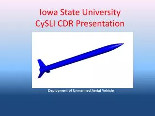
Payload Housing and Integration • Folds up while inside upper airframe • A torsional and tensional spring in each leg creates a sprawling motion once payload is deployed • Wheels allow easy vertical sliding of payload • Rests in “shoes” during flight, which are fixed to inside of Upper Airframe • Tube is made out 1/8” T6-6061 Aluminum, with an outside diameter of 3.25” • Legs are made out of 1/16” Aluminum U-Channel • *Note* - video cameras, parachute compartment, and payload lid not shown in this drawing
Payload Electronics • Contains two redundant R-DAS Tiny altimeters that control the payload’s main parachute deployment and record all sensor data. Each R-DAS Tiny has its own 11.1V flight battery • Contains two analog temperature and two analog humidity sensors • Contains a GPS and transceiver powered by the batteries on their respective boards • Similar structural design as the Avionics Bay • Two video cameras attached to the outside of the payload bay
Payload Lid • Serves as mount for UV sensors and solar cells
Outline • Vehicle Design • Payload Design • Recovery System • Component Testing • Subscale Flight • Simulations • Outreach • Future Work
Recovery Method • Two recovery systems because of payload separation • Redundant PerfectFlite altimeters will control the rocket’s dual deployment • Redundant R-DAS Tiny altimeters will control the payload’s dual deployment • The payload will use streamers as a drogue to prevent shading of the solar and UV sensors • 5/8” tubular nylon will connect all sections of both rocket and the payload to their respective parachutes Rocket Drogue: 36” round Descent Rate: 64 ft/s Rocket Main: 96” round Descent Rate: 21 ft/s Payload Drogue: Heavy Duty Streamers Descent Rate: Undetermined Payload Main: 36” round Descent Rate: 19 ft/s
Outline • Vehicle Design • Payload Design • Recovery System • Component Testing • Subscale Flight • Simulations • Outreach • Future Work
Wind Tunnel Testing • Undergraduate low-speed wind tunnel on campus • Open-circuit, max speed of 120 mph • Test section: 12”x12” cross-section, 24” long
Experiment 1 - Fins With Varied Paint Combinations • Fin 1 – Control Fin • Fin 2 – Paint • Fin 3 – Primer & Paint • Fin 4 – Primer, Paint, & Gloss
Experiment 2 – Fins With Varied Shape Combinations • Fin 1 – Control Fin • Fin 5 – Rounded LE • Fin 6 – Tapered TE • Fin 7 – Rounded LE and Tapered TE
Wind Tunnel Results • Greatest Reduction in drag from the rounded LE, tapered TE fin • The tapered TE fin showed no drag reduction at all. • The fins that were painted but not glossed showed higher drag reduction that the glossed fin • Drag Coefficient calculation assumptions: • There is a linear relationship between compressor speed and airspeed • The structure holding the fins produced negligible drag in addition to the fin. • For higher accuracy, the drag from the test structure needs to be accounted for and the speed airspeed needs to be calibrated properly
Recovery System Testing • Dual Deployment Test with PerfectFlite • Hooked up Christmas lights as imitation igniters • Placed altimeter inside avionics bay • Extracted air from the tube and both Christmas bulbs lit up after air was passed back into the tube and air pressure was restored • The data was checked to ensure that the igniters were fired at the correct altitude • Subscale ejection charge testing • The first charge needed to eject the payload at least 15 feet from the rocket without causing overwhelming stress on any components • The second charge needed to eject the lower airframe at least 15 feet from the rocket without causing overwhelming stress on any components • Three grams of black powder met the criteria of both charges, and worked successfully in the subscale test flight
Payload Testing • Temperature and humidity sensor testing complete by seeing change in voltage in varying temperature and humidity climates • GPS and XBEE are now functioning correctly with the software on the ground after much trial and error
Vibrations Testing • Evaluate deformation characteristics during flight • Are modal frequencies within gust spectrum? • What mode shapes result from stiffness/mass distribution? • Ground vibration test (GVT) • Soft support was bungee • Sine sweep from 10-1500 Hz • 2 lb force actuator • Impact hammer • Measured vibrations • Laser Doppler vibrometer (LDV) • Accelerometers • Load cell measured force input • Utilized subscale rocket after launch
Vibrations Testing Experimental setup Laser on structure Actuator and load cell
Vibrations Testing • Found variety of mode shapes • Similar to 2 beams cantilevered around high stiffness near avionics bay • Mode shapes indicated tip deflections were not large even with pounds of force • No additional stiffness seems required for flight safety during short portions of flight with high dynamic pressure
Outline • Vehicle Design • Payload Design • Recovery System • Component Testing • Subscale Flight • Simulations • Outreach • Future Work
Subscale Flight • January 8th, at NEFAR • 18 mph winds, 10° launch angle • 88.5” length, 3” diameter, 8.75 pounds • The Gorilla I235 motor was used, and the same motor retention concept for the full scale was used • Successful dual deployment and payload separation, rocket’s main parachute deployed at 300 feet to avoid excessive drift • Payload contained only a main parachute that was deployed at apogee, which resulted in excessive drift of the payload • The payload spun at a relatively fast rate while descending, which could be an issue for our full scale payload which will need to take quality video and land without turning over; a swivel bolt has been considered to mitigate this problem
Subscale Static Test • Created our own static test stand • Tested the I235 to input into our MATLAB program to simulate subscale flight • We also plan to test our full scale motor
Subscale Altitude Results • Maximum altitude from the PerfectFlite was 890 feet • The main parachute was deployed at 300, as can be seen from the graph below • The main chute descent rate calculated from this data was about 20 ft/s, which is in the desired range
Outline • Vehicle Design • Payload Design • Recovery System • Component Testing • Subscale Flight • Simulations • Outreach • Future Work
MATLAB 2DOF • MATLAB has been updated to include downrange motion of the rocket • Downrange motion is only affected by launch angle; no angle of attack • Better reflection of physical system • Still lacks: • Winds • Parachutes • Oscillations • Rotations
Drag Coefficient • Lack of knowledge of the true coefficient of drag prevents accurate simulation. True for RockSim and MATLAB • In order to achieve a better estimate of the drag coefficient, the max altitude of the MATLAB 2DOF was matched to the max alt. of the subscale launch altimeter data
Full Scale Max Altitude Optimization • Ran RockSim model at various wind conditions with the L1400 • Found that, to minimize downrange drift, the launch angle into the wind should increase by one degree for every mph of wind • Found the additional mass needed to reach a mile depending on the launch angle • On launch day, once launch conditions are known, the additional mass needed will be added with modeling clay in between the top two centering rings (near the center of gravity), then the top centering ring will be screwed in place
Outline • Vehicle Design • Payload Design • Recovery System • Component Testing • Subscale Flight • Simulations • Outreach • Future Work
Educational Engagement • Presented to 150 5th graders at Hidden Oak Elementary School for one hour • PowerPoint presentation taught students about the basics of rocketry, how to get involved, and how to remain safe • Three model rockets were launched to give the students an first-hand example of rocketry
Educational Engagement • Presented to sixty 4th-8th graders at Millhopper Montessori School (private school) for one hour • Similar presentation to the one at Hidden Oak, but the subscale rocket was also shown • Like at Hidden Oak, three model rockets were launched in a nearby field for the students to see
Educational Engagement • Thank you note from Hidden Oak Student
Educational Engagement • Engineering-Fair • This department wide event occurs on February 22nd and 23rd and brings in elementary, middle, and high school students from the local area to teach them about engineering • The USLI team plans on sharing a booth at this fair with AIAA and will teach students the basics of rocketry and what to do in school to better their chances at getting into UF • Aerospace Day • UF AIAA chapter brings together middle school students from around the local area to build gliders, bottle rockets, and small model rockets • The USLI team will provide support in model rocket building and launching and will also launch some higher power rockets to influence the students to pursue engineering studies. Date is uncertain
Industry • Presented to three SpaceX employees • Used PowerPoint to describe the work done over the past two years, and what the team is working towards • Showed the subscale rocket, our static test stand, and the data from the wind tunnel experiments • Also plan to present to Northrop Grumman representatives in late February
Outline • Vehicle Design • Payload Design • Recovery System • Component Testing • Subscale Flight • Simulations • Outreach • Future Work
Continue MATLAB adjustments • Parachutes added to modify descent rate – improve downrange displacement estimation • MATLAB model will be extended to 3DOF • More altimeter data collected from second subscale launch and full scale rocket launch to adjust coefficient of drag • Continued wind tunnel testing to compare experimental CD values with RockSim CD values • Compare with RockSim for various wind speeds • RockSim and MATLAB models compare to launch data. Best-fit determined
Payload Testing • Sensor conversion constant verification • Solar cell has range of 430 to 1100 nm. Test the voltage to W/m2 conversion constant • UV sensor voltage to W/m2 conversion constant (1.962) • Sensor-to-RDAS configuration • R-DAS Tiny altitude testing • Will be tested with second subscale flight and compared with PerfectFlite altimeter • Video camera vibration testing • Battery voltage check
Recovery System Testing • Full scale ejection charge ground testing • Need parts to be ejected at least 15 feet apart from each other without significantly damaging components • Payload streamer descent rate verification • Need a descent rate between 50 and 100 ft/s • Payload bay separation testing • Sliding in and out of upper airframe, legs springing out • Payload landing testing • At a maximum allowable velocity of 22 ft/s • With horizontal motion, rotation, and tilt angles • R-DAS & GPS testing in Avionics Bay and Payload Bay
Static Motor Testing • The L1400 will be tested on a different test stand provided by our mentor, Jimmy, which is capable of such large motors • This will test our ignition method • This will help verify which motor characteristics that should be trusted- the official one provided by the NAR or the one provided by RockSim • The motor will also be tested with the retention device connected, just in case it effects the exhaust flow at all