Download
1 / 19
190 likes | 381 Views
4: From x-ray to image – Computed Tomography. What factors influence contrast in x-ray imaging ? Beam hardening Sensitivity and resolution considerations What is the fundamental basis for image reconstruction using x-ray absorption ? Radon Transform

E N D
4: From x-ray to image – Computed Tomography • What factors influence contrast in x-ray imaging ? Beam hardening Sensitivity and resolution considerations • What is the fundamental basis for image reconstruction using x-ray absorption ? Radon Transform • How can x-ray images be reconstructed? Sinogram Backprojection vs. filtered backprojection Central Slice Theorem • Examples • After this course you • Understand the consequences of the Bremsstrahlung continuum on image contrast • Understand how Compton scattering reduces image contrast and how its influence can be reduced • Are familiar with the Radon transform • Understand the principle of matrix reconstruction and backprojection • Understand the major mechanisms leading to CT contrast
Computed Tomographyinvented 1971 Primitive pancreatic lesion (neoplastic) Godfrey Hounsfield Allan Cormack Nobel prize 1979 First clinical CT- 1972 engineer physicist Physiology and Medicine
CT of animal models transgenic mice and cancer models kidneys with IV contrast rat spine micro-CT scanner abdomen heart and lungs full body skeleton microCT (~50 µm spatial resolution) Mouse: blood vessels (red)
4-1. What does absorption in the real world imply ?Linear attenuation coefficientm Contrast is “well-defined” for monochromatic x-rays n-dn n But, µ=f(En,Z, r) μ : linear attenuation coefficient Unit: [cm-1] The measurement that is wanted: m(x,y) What is measured: n(x) dx If µ is constant in x Two consequences: Beam hardening Depth dependent contrast (m for a homogeneous object of thickness x)
What does the Energy Spectrum of an x-ray tube really look like ?filtered Bremsstrahlung and characteristic emission i(En): complex function i(En) Eeff Interaction with orbital electrons Define effective photon energy Eeff Bremsstrahlung continuum Soft x-rays (low energy) Hard x-rays (high energy) Maximal x-ray energy is = kinetic energy of e- (eVcathode) Eeff is increased by instrument (filtering of soft x-rays) Minimal energy is zero, but: Soft x-rays (low energy) are filtered by instrument
What is the consequence of energy-dependent absorption ?Beam Hardening - Effective energy depends on depth • A similar consequence arises in tissue: • Ideal: Monochromatic x-rays (En(l) = d(l0)) • Reality: Polychromatic, multienergetic i(En) • Absorption is not uniform with En • Contrast changes with large objects and depth • Excessive radiation dose to superficial tissue “Solution”: Reduce i(En) for soft x-rays (e.g. 3mm Al eliminates 90% of 20keV photons)
How does x-ray scattering impact CNR ? Scattering increases with FOV (field-of-view) of irradiation Further reduction of image contrast Solution: Anti-scatter grid (collimator) Object (lesion) Photoelectric effect: complete absorption of photons →Object (lesion) easily detected With En↑: Compton scattering → increased masking of object. High Z, r: stop x-rays Collimation principle: establishes directionality of x-rays Slice selection Detector
How is CNR quantified ? • Signal: I(d) (no. photons detected) I0(no. photons irradiated) • Contrast: DI(d) due to µ(d) differences • i(En), mC produces reduced contrast • Compton scattering: Antiscatter grid CT intensity can be measured in absolute terms (CT-number) Soft tissue: Typically has weak contrast (small Hounsfield units) • HU : attenuation normalized to water (0) • range from -1000 (air) to +3000 (bone and contrast agents) • soft tissues: -300 to +100
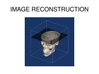
4-2. What is the basis of image reconstruction ? The Radon transform Dy Dy … Considering a two-dimensional objet: Given a certain beam intensity (no. of photons) I at a given position y, I(y0), the beam intensity at y+Dy is Recursive application to derive I(y0+2Dy) I0: intensity of incident x-ray beam I0 I(y) x y y0 Radon transform g(x) Definition Radon transform of a point-like homogeneous object rectangular object lim Dy→0 g(x)
Does each pixel have a unique trajectory ?Sinogram Radon transform of a circular object f Radon transform = projection of object Trajectory: Rsin(f+f0) Each point in space is uniquely represented by Amplitude R and phase f0 of sinusoidal trajectory in Sinogram (sic!): (x,y) → (R,f0) Detector: is moved in circular motion around object (indicated by angular position f)
Can a CT image be constructed by Matrix inversion ? Decomposing an object into a 2x2 matrix requires a minimum of 4 measurements: ln(I1/I0) = -m1Dx-m2 Dx ln(I2/I0) = -m3Dx-m4 Dx ln(I3/I0) = -m1Dy-m3 Dy ln(I4/I0) = -m2Dy-m4 Dy Setting Dx=Dy yields a linear 2x2 inversion problem linking mk to Ik In principle such an n2 matrix can be inverted. Too complex, computationally intensive and unstable CT was introduced in 1970 simple reconstruction algorithm!
y’ x’ 4-3. What algorithm is adapted to 1970’s computing power ?Backprojectionreconstruction Basic reconstruction principle: Along the measured projection direction fill in each pixel constant numbers corresponding to the Radon transform (projection intensity). Repeat for next orientation of the projection, sum the values in overlapping pixels. Illustration with gray shades (point-like object): 1 1 1 1 1 1 1 1 1 1 1 1 1 1 2 4 Projections 2 Projections 180 backprojections: reconstruction is complete. 1st 60 Projections the next 60 8 Projections 16 Projections
Why does simple Backprojectionhave poor spatial resolution ? Backprojection has poor spatial resolution: Solution ? Reconstruction of a point-object falls of with 1/r WHY? The reconstruction falls off with 1/r (in analogy to the decrease of light intensity in 2D) df dxdy=dA=rsin(df)drrdfdr dA r Number of rays (projections): constant with df rdf But: pixel size = dxdy dA = const No. of rays 1/r df dr r
How can good image resolution be maintained ? Filtered Backprojection Example: Reconstruction of a slice from projections
k-space (Fourier space) Image space ky y kx x MRI: Acquired Data Final Image (CT: acquired data) How is Backprojection linked to Fourier transform ? Central Slice Theorem kx=0 FT FT of projection → 1 line in k-space IFT Reconstruction using FT : artifacts See also: Signals and Systems (SV)
X-ray CT : Examples (Human) Bone (calcification) : bright (high absorption) Imaging of mummified bodies Different densities of tissue give inter-mediate results Air is dark Dislodged arrow head
CT: Examples (mouse) Pre- Post-contrast • 3D CT scan of rodent spine • treated with human mesenchymal stem cells (transduced with the human BMP-9 gene via an adenoviral vector) • significant bone formation at the treatment sites (arrows) 13µm micro CT of mouse placenta vasculature Micro-CT of mouse femor bone
CT: Summary • Main contrast is bone vs. soft tissue (or air) (calcium content i.e. e- density r) • Contrast agents (increase Zeff) allow depiction of vessel architecture and lesions • SNR and CNR: • Intensity can be increased by cathode current • High spatial resolution possible • (limited only by radiation dose in humans) Fish larvae Insect with iodine contrast agent
First Generation Parallel beam design One/two detectors Translation/rotation 2nd Generation Small fan beam Translation/rotation Larger no. of detectors 3rd Generation Multiple detectors Large fan beam 4th Generation Detector ring Large fan beam How have CT scanners evolved ?Generations of CT scanners