Download
1 / 12
120 likes | 334 Views
Lecture #21 EGR 260 – Circuit Analysis. Phasor Analysis. “I have found the equation that will enable us to transmit electricity through alternating current over thousands of miles. I have reduced it to a simple problem in algebra.” Charles Proteus Steinmetz.

E N D
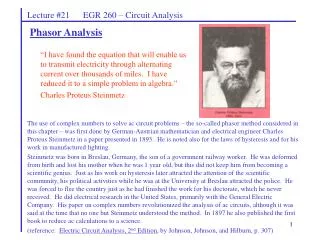
Lecture #21 EGR 260 – Circuit Analysis Phasor Analysis “I have found the equation that will enable us to transmit electricity through alternating current over thousands of miles. I have reduced it to a simple problem in algebra.” Charles Proteus Steinmetz The use of complex numbers to solve ac circuit problems – the so-called phasor method considered in this chapter – was first done by German-Austrian mathematician and electrical engineer Charles Proteus Steinmetz in a paper presented in 1893. He is noted also for the laws of hysteresis and for his work in manufactured lighting. Steinmetz was born in Breslau, Germany, the son of a government railway worker. He was deformed from birth and lost his mother when he was 1 year old, but this did not keep him from becoming a scientific genius. Just as his work on hysteresis later attracted the attention of the scientific community, his political activities while he was at the University at Breslau attracted the police. He was forced to flee the country just as he had finished the work for his doctorate, which he never received. He did electrical research in the United States, primarily with the General Electric Company. His paper on complex numbers revolutionized the analysis of ac circuits, although it was said at the time that no one but Steinmetz understood the method. In 1897 he also published the first book to reduce ac calculations to a science. (reference: Electric Circuit Analysis, 2nd Edition, by Johnson, Johnson, and Hilburn, p. 307)
Lecture #21 EGR 260 – Circuit Analysis Read: Chapter 9 and Appendix B in Electric Circuits, 8th Edition by Nilsson Development of “phasor analysis” AC circuit analysis (or phasor analysis) is very similar to DC analysis, but the justification for the method of analysis is somewhat complicated. Recall from a study of differential equations that the forced response to a circuit will be in the form of the input (+ derivatives of the input). So if the input is sinusoidal, the output must also be sinusoidal as shown below. Note that the input and the output on differ by the magnitude and the phase. Recall that polar numbers are represented by a magnitude and a phase angle. (More on this shortly)
Phasor– a complex number in polar form representing either a sinusoidal voltage or a sinusoidal current. Symbolically if a time waveform is designated at v(t), then the corresponding phasor is designated by . Lecture #21 EGR 260 – Circuit Analysis Examples: Convert to the other notation (time waveform or phasor) Solving complex equations Two equations can be generated from a single complex equation by equating the real and imaginary parts of the equation. Example: A + jB = C + jD (one complex equation) so A = C and B = D (real parts of the equation) (imaginary parts of the equation)
Lecture #21 EGR 260 – Circuit Analysis Further justification for “phasor analysis” Suppose that we replaced a real sinusoidal forcing function v(t) = Vpcos(wt + ) with a complex forcing function V(s) whose real part equals v(t). Define V(s) = Vpej(wt+) = complex forcing function. Recall Euler's Identity: e±jA = cos(A) ± jsin(A) So V(s) = Vpej(wt+) = Vp[cos(wt + ) + jsin(wt + )] And if the real part of V(s) is designated Re[V(s)] then Re[V(s)] = Vpcos(wt + ) = v(t) Replacing sinusoidal forcing functions with complex forcing functions will result in a cancellation of exponential terms leaving only phasor terms. Example: Use KVL on the circuit below to show how the phasor equation can be developed.
Lecture #21 EGR 260 – Circuit Analysis Before we get into the details of phasor analysis, we need a method of representing components in AC circuits. We will introduce a new term called impedance. Complex Impedance Z = impedance or complex impedance (in ) Note that the relationship above is similar to Ohm’s Law. Now we will define impedance for resistors, inductors, and capacitors. Resistors: If i(t) = Ipcos(wt + ), find v(t) and show that
Lecture #21 EGR 260 – Circuit Analysis Inductors: If i(t) = Ipcos(wt + ), find v(t) and show that Capacitors: If v(t) = Vpcos(wt + ), find i(t) and show that
Lecture #21 EGR 260 – Circuit Analysis Example: Find I(t) in the circuit below using phasor analysis.
Lecture #21 EGR 260 – Circuit Analysis KVL and KCL in AC circuits: KVL and KCL are satisfied in AC circuits using phasor voltages and currents. They are not satisfied using the magnitudes of the voltages or the currents. Example: For the previous example, show that:
Lecture #21 EGR 260 – Circuit Analysis Phasor diagrams: KVL and KCL are only satisfied by phasors as indicated above, but it can be difficult to see exactly why certain voltages combine or cancel in some circuits. A phasor diagram is a vector diagram that illustrates graphically exactly how the phasors combine. Phasor diagrams will help the student to get a better feel for what happens when AC voltages or AC currents combine. Example: For the previous example, show that using a phasor diagram.
Lecture #21 EGR 260 – Circuit Analysis AC Circuit Analysis Procedure: 1) Draw the phasor circuit (showing voltage and current sources as phasors and using complex impedances for the components). 2) Analyze the circuit in the same way that you might analyze a DC circuit. 3) Convert the final phasor result back to the time domain.
Lecture #21 EGR 260 – Circuit Analysis Example: Analyze the circuit below using phasor analysis. Specifically, A) Find the total circuit impedance B) Find the total current, i(t) C) Use current division to find i1(t) and i2(t) D) Show that KCL is satisfied using current phasors, but not current magnitudes.
Lecture #21 EGR 260 – Circuit Analysis Example: (continued) E) Show that KCL is satisfied using a phasor diagram.


