Download
1 / 25
250 likes | 405 Views
Video Display and Audio Systems. Basic PC Maintenance, Upgrade and Repair Mods 1 & 2. Display Concepts. There are a number of features common to all monitors. These features such as dot pitch and size, greatly affect the quality of the picture, as well as the price the user pays for it.

E N D
Video Display and Audio Systems Basic PC Maintenance, Upgrade and Repair Mods 1 & 2
Display Concepts • There are a number of features common to all monitors. • These features such as dot pitch and size, greatly affect the quality of the picture, as well as the price the user pays for it. • Monitor Size – Standard sizes are 14”, 15”, 17”, 19”, and 21”. It is measured from one corner to the opposite corner of the monitor. • Dot Pitch – the distance measured in millimeters between two color dots on the screen. It directly affects the quality of the image displayed. • Generally, the smaller the dot pitch, the sharper the image displayed. • Common dot pitch is from 0.28 mm to 0.25 mm. It cannot be adjusted.
Display Concepts • Color Display Values – The color display quality is determined by the number of bits used to represent the individual colors of red, green, and blue. • This can also determine the possible number of color shades. • A byte contains 8 bits. • There are 256 combinations of 1’s and 0’s available with 8 bits. • This means that an 8 bit color pattern can reproduce 256 intensities of a specific color. • By mixing the intensities of red blue and green, other colors can be produced.
Display Concepts • Display Resolution – this term refers to the amount of detail a monitor is capable of displaying. • The term is also used by printers, digital cameras, etc. • The higher the value, the better the detail and quality of the picture. • Resolution is measured in pixels. A pixel is the smallest unit of color in a screen display.
Types of Displays • There are a number of different types of display systems for computers. • The two most common types are . . . . • CRT – Cathode Ray Tube • LCD – Liquid Crystal Display • Cathode Ray Tube – A picture tube in which a beam of electrons sweeps across a glass tube, exciting phosphorus dots in the screen. • Liquid Crystal Display – A type of monitor that uses polarized light passing through liquid crystal to create images on screen.
CRT’s • A CRT has two ends, Cathode and Anode
CRT’s • The Anode has a positive voltage potential between 16,000 to 25,000V.
CRT’s • A filament connected to the cathode is heated and it emits electrons. These electrons form a cloud.
CRT’s • The electrons are attracted to the positive Anode, are accelerated and focused into a pencil beam.
CRT’s • The accelerated electrons collide with the phosphor coating on the Anode and emit light.
CRT’s • Horizontal and vertical deflection coils position the pencil beam in the desired location on the phosphor screen
CRT’s • The pencil beam is moved across the screen and down in precise increments. • 525 horizontal lines are completed 60 times every second. The movement of the pencil beam uses the terms trace, retrace and blanking. • Trace is when the line of video is being produced. • Retrace is when the pencil beam is moved back to its horizontal starting position. • Blanking is the blocking of the pencil beam during retrace so it is not seen on the screen. • Color systems work similar, except there are three electron pencil beams being directed at pixels containing red, blue and green phosphors. • The intensity of each beam on the individual phosphors creates the specific color in that location
LCD’s • The LCD operates off of two principles: • Polarized light. • The effect of an electrical voltage applied to a crystal structure. • A typical light beam is composed of numerous waves of light. • They travel in parallel, but at different wave angles. • If a thin slot is cut in a material such as metal, only light waves with an angle matching the slot can pass through. This is polarized light. http://www.olympusmicro.com/primer/lightandcolor/polarization.html • When an electrical voltage is applied to a crystal, the crystal changes shape slightly or twists. • The amount of twist is directly related to the amount of voltage applied. • Light normally passes through the crystal in a straight line. • When a light is shined through a crystal and a voltage is applied to the crystal, the angle of the light wave changes as it passes through. http://electronics.howstuffworks.com/lcd3.htm
LCD Structure Sandwiched structure
Passive and Active Matrix Displays • The two types of LCD displays are Passive and Active Matrix. • Both use matrixes to determine how to select individual pixels • A passive matrix is a grid of semitransparent conductors that run to each crystal. It is divided into columns and rows. • Transistors running along the top and side of the display are activated in such a way as to activate a specific pixel (crystal) area. http://electronics.howstuffworks.com/lcd7.htm • An active matrix display uses a matrix that has a transistor that activates at each pixel (crystal) location. • The most common type is TFT (thin film transistor) LCD displays. It offers a brighter image that responds more quickly to changes. • There are over a million transistors spread across a display, three for each pixel (red, green, blue).
Other LCD Concepts • Contrast Ratio – a numeric expression in the form of a ratio that that describes the amount of contrast between the darkest and the lightest pixel in the image. • The higher the number the better. • Typical range is from 200:1 to 600:1 • A contrast ration of over 500:1 is considered a high quality display. • Brightness – in an LCD display, this is produced by the fluorescent backlight. • It determines the maximum amount of brightness produced in the display. • Levels typically range from 200 cd/m2 (candela per square meter) to 250 cd/m2.
Other LCD Concepts • Viewing Angle – a measurement of the angle at which a person can adequately see an image on a display without it looking excessively distorted. • Early LCD displays were quite limited in this area. • Today, most have a very acceptable viewing area. • Minimum around 150°, maximum around 170° (possibly even more). • Pixel Pitch – similar to CRT dot pitch, it is the distance between two same color pixels on the display area (i.e. two red pixels, two blue pixels, etc.) • Each color pixel is composed of three pels, one pel for each of the three colors that compose a pixel. • Pixel pitch is expressed in millimeters (mm) per inch.
Other LCD Concepts • Native Resolution – The resolution that matches the pixel design of the display • Although an LCD display is capable of showing a number of different resolutions, it will have the best images at its native resolution. • Response Time – the amount of time it takes a TFT pixel to display after a signal is sent to the transistor controlling that pixel. • Measured in milliseconds (ms). • A typical response is 15 to 40 ms. • The lower the response time, the better quality of the unit, especially with animation. • Aspect Ratio – A ratio of a display areas height and width. • Standard is 4:3 • New HD TV uses 16:10
Video Adapter Cards • Monitors can attach to computers in one of two ways: • It can plug into a video adapter card inserted into an AGP or PCI slot on the motherboard. • It can attach directly to the motherboard (that has integrated video components built in). • The heart of the video adapter card is the special IC chip known as a digital to analog converter (DAC). • It converts the computer’s digital video signal into an analog signal for the computer monitor. • The DAC can consist of one chip, or three, one for each color. • The video card also contains RAM, ROM, a video processor, and BIOS.
Pin Description • Red Video • Green Video • Blue Video • Monitor ID Bit 2 (Ground) • Ground • Red Return (Ground) • Green Return (Ground) • Blue Return (Ground) • Key (not used) • Sync Return (Ground) • Monitor ID Bit 0 (Ground) • Monitor ID Bit 1 (Not Used) • Horizontal Sync • Vertical Sync • Not Used Video Adapter Cards • A VGA monitor uses a 15-pin connector to connect to the video card.
Video Adapter Cards • Video cards are installed in PCI or AGP motherboard slots • AGP – Accelerated Graphics Port – is a slot used specifically for video cards and produces the highest quality result of the two technologies. • AGP is designed with graphics as a priority, using a computer’s memory to work more effectively with graphics. • AGP also has a faster bus speed.
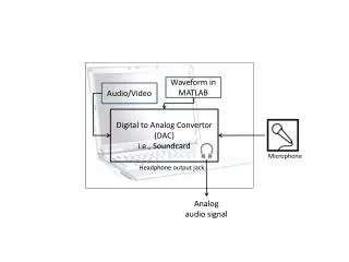
Audio Systems • Audio is the second half of the multimedia experience. • All PC’s come with a small internal speaker, but that is not enough for most users. • Fancy sound cards, subwoofers, speakers and microphones have become standard equipment on many systems. • The human ear can detect sounds from approximately 20Hz to 20kHz. This is called the frequencyresponserange of the human ear. Sound waves (vibrations) above or below this range go undetected. • To convert analog sound to digital, a device called a Analog to Digital Converter (ADC) is needed. The method used with this ADC is called sampling.
Sampling • Sampling is the measurement of an analog signal at regular intervals. It is required to convert an analog signal into a digital signal. • The quality of the conversion is based on two main things: • Sampling rate • Number of bits used to represent the voltage level of the signal • A high sampling rate gives a better representation of an analog signal shape, but also requires more memory and hard disk space. • The number of bits available to represent analog voltage levels also can require more memory and hard disk space. • Older systems used 8 bits, while systems today use 16 bits. • 16 bits can much better represent the original sound.
8-bit vs. 16-bit • Sounds recorded with 8 bit technology is limited to 256 different voltage levels, or binary codes, required to store a binary image of the sound wave sample. • 16 bit sound cards can use 65,536 binary codes to represent the analog voltage level during sampling. It is a more detailed representation of the sound wave pattern. • Another name given to the number of bits used is “resolution”.
Audio Devices • Microphone – a simple electronic device that converts sound waves in to electrical energy. • It converts air vibrations that strike it into voltage levels that are directly proportional to the strength and frequency of the vibrations • Speakers – a device that converts electrical energy to sound energy (waves) • The stored digital code representing the sound waves is converted by the sound card into an analog signal which is then sent to the speakers • The speaker cone vibrates at a rate proportional to the strength and frequency of the analog electrical signal • Sound Cards – Device that converts analog audio to digital audio and digital audio to analog audio. The output is a low level, so an amplified speaker system is required. • Most sound cards today are purchased as PCI adapter cards. This means they are usually PnP technology. • System resources (IRQ, DMA, I/O, Memory) are automatically detected and assigned.