Download
1 / 17
180 likes | 234 Views
Learn about texture mapping to enhance surfaces. Explore subdivision surfaces, pelt mapping, blending techniques, and more for seamless results. Improve distortion, minimize seams, and maintain smoothness on arbitrary topologies. Discover advanced methods for better texture control with minimal computation. Visit the link for detailed insights.

E N D
Texture Mapping by Model Pelting and Blending Deva Ramanan Hao Zhang
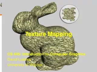
Texture mapping • Improve surface appearance • Versatile: image map, displacement map, reflection map … • Relative small amount of computation (from Pixar shutterbug image series)
Texture mapping (contd.) • Requires “good” parameterization • Minimize distortion • Appears to be seamless
Subdivision surfaces • One single mesh for any topology • Multiple NURBS patches • Maintain smoothness (static and animated) • (u,v)-parameterization • Tensor product B-Spline patches • Shapes of arbitrary topology • Cf. “Character animation” (SS98) (SS98)
Texture mapping on subdivision surfaces • 3D Solid Textures • Multiple local textures • Blend overlapping regions at the seam • Goals (again): • Minimize distortion • Seam blending http://graphics.eecs.wsu.edu/apst/
Texture coordinates • Linear interpolation [Stam98] • texture coords as local (u,v) parameterization • yields C1 interior and C0 cross-boundary • Catmull-Clark on scalar field • position (x,y,z) position+texture (x,y,z,s,t) • subdivide in 5D • yields C2 interior and C1 on extra-ordinary points • needs texture coordinates on M0 (SS98)
Texture mapping analogy: The pelt • Initial control mesh ~ rubber sheet • Stretch mesh to form a pelt • Paint texture on the pelt
Pelting: The Cut • Cut: User specified connected tree of edges
Pelting: Implementation • Approximate rubber sheet by a spring-mass system • Distortion measure: • Elastic energy • Scale invariance
Simulate a spring-mass system • System evolves so as to minimize energy
Blending Texture: Approach -Uo: Pelt Region • Split M0 into 2 overlapping regions: -U1: Patch Region • Use blend functions b0() & b1() along overlapping regions
Example Patch C0 + C1 + C2 + C3= patch region
Review: Domain of Control P A B C D • 2D Cubic B Splines: • Catmull/Clark surfaces: P
Blend Function C0 • Pelt, Patch, and Overlapping Regions surrounding the Cut C1 C2 C3 C4 • b1= cubic B-spline • b0 = 1 - b1
Evaluation • Pelting: • Novel 3D Spring Mass implementation eliminates “buckling” [Maillot et al 93] • Seam blending: • Painted textures • Weaknesses: • Tiled/tesselated pattern • low polygon count meshes
Conclusion • Ultimate goal: • Minimum distortion • texture coordinate control http://www.tfe.umu.se/courses/systemteknik/Multimed2/