Download
1 / 17
170 likes | 346 Views
State of the art in Organic Photovoltaic Devices. Brian A. Collins. Background of Excited States. Molecular Representation. -. Polarons. +. Exciton. +. -. Excited States Induce Geometrical Relaxation. Transport. Polypyrrole oligomer various charge states.

E N D
State of the art in Organic Photovoltaic Devices Brian A. Collins
Background of Excited States Molecular Representation - Polarons + Exciton + - Excited StatesInduce Geometrical Relaxation Transport Polypyrroleoligomer various charge states X. Lin et. al., Int. J. Quant. Chem. 102, 980 (2005)
Device Background • Photon Absorption -> Excitons • Exciton Separation -> Polarons • Partial separation by ultrafast (~45fs)“Charge Transfer” into “Bound Polarons” or “Polaron-Pairs” or “Exciplex” • Charge (polaron) Transport • Potential trapping at polymer dead-endsor recombination at polymer:fullerene interfaces • Charge Collection at Electrodes • Potential recombination at interface due to mutual contact of polymer & fullerene V. Shrotriyaet. al., Adv. Funct. Mater. 16, 2016 (2006) HOMO LUMO J. A. Barker et. al., PRB 67, 075205 (2003)
Power Conversion Efficiency (PCE or ηP) Four-terminal measurement Current vs. Applied Voltage VOC • PCE = JSC*VOC*FF/Pin • Pin ~ 100mW/cm2, AM1.5 spec • High Fill Factor (FF) = High RSH and Low RS • External Quantum Efficiency (EQE) (or IPCE) • Electrons out / photons in • PCE(E) • Internal Quantum Efficiency • Electrons out / photons absorbedvs. Energy FF Max Power JSC V. Shrotriyaet. al., Adv. Funct. Mater. 16, 2016 (2006)
Current avenues at improving PCE • Increasing Voc • Better Band alignment at all interfaces • Lower Polymer HOMO (given same electrodes) • Increasing Jsc • Better Morphology through best solvents, annealing, best blend ratio • Increasing Absorption • Smaller Band Gap polymers • Sorting the carriers • Layers to block wrong charges(PEDOT & TiOx) • Mostly Phenomenological K. Vandewal et. al., (2009) DOI: 10.1038/NMAT2548 Can you read these tea leaves? T. M. Clarke et. al., Adv. Fucnt. Mater. 18, 4029, (2008).
Nature Photonics, 26 April 2009 Bulk heterojunction solar cells with internalquantum efficiency approaching 100% Sung Heum Park1,2, Anshuman Roy1, Serge Beaupre´3, Shinuk Cho1,2, Nelson Coates1, Ji Sun Moon1,2, Daniel Moses1, Mario Leclerc3, Kwanghee Lee1,2*and Alan J. Heeger1,2* UCSB, Gwangju Institute of Science and Technology South Korea & University of Laval, Canada
Active Materials • Polymer: PCDTBT (alternating copolymer) • (relatively) small bandgap, deep HOMO (for better Voc) • Higher absorption and conductivity with PC70BM vs. PC60BM
TiOx Hole Blocking Layer • Eliminates recombination at the cathode • Electric field spacer to maximize absorption
Solvent Dependence • Dichlorobenzene produces best morphology (~20nm phase separation) • Low exciton mobility and lifetime limits diffusion length to ~10nm in OPVs • High FF & Jsc implywell-connected percolation networks? • No hypothesis asto mechanism DefocusedTEM AFM phase
Polymer:Fullerine (Blend) Ratio • Progression of increased phase separation w/PCBM content • (1:4) “fibrillar” structure in PCDTBT caused by excess PCBM • Why is high PCBM content better? • Is higher PCBM content better?
Internal Quantum Efficiency • IQE(Energy) = IPCE/Absorption • Nearly Zero Field-dependent exciton splitting • Every absorbed photon is converted to electrical power • Morphology is optimized F8BT:PFB
Interesting Points • Stability and Longevity issues • Large Potential for OPVs Annealing Amorphous Polymer Single Wavelength Efficiency
Advanced Materials, 2010 For the Bright Future—Bulk Heterojunction PolymerSolar Cells with Power Conversion Efficiency of 7.4% Yongye Liang, ZhengXu, Jiangbin Xia, Szu-Ting Tsai, Yue Wu, Gang Li,* Claire Ray, and Luping Yu* University of Chicago & Solarmer Energy Inc.
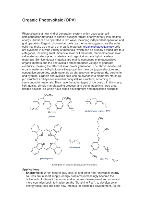
Active Materials • PTB: theino[3,4-b]thiophene, benzodithiophene alternating copolymer • Fluorene (electron withdrawing) deepens HOMO • Better fullerine miscibility • Smaller bandgap (1.6eV) allows for better absorption spectrum • Rigid backbone for higher mobility • Crystallizes face down (diff. from P3HT) From CV measurements Y. Liang et. al., JACS 131, 7792 (2009)
Nominal Solvent & Blend Ratio Characterization • DCB = Dicholorbenzene • CB = Chlorobenzene • DIO = Diiodoctane
Nanoscale Morphology TEM Micrographs 90% Internal Quantum Efficiency (“champion” cells) CB • Correlation of morphology and performance with solvent (not well characterized or understood) 200nm CB - DIO 200nm