Download
1 / 18
180 likes | 273 Views
This collaborative study focuses on the development and commissioning results of the SRF gun using a Pb cathode in an Energy Recovery Linac (ERL). The study demonstrates the feasibility of using ERL technology for future synchrotron light sources, showcasing the electron source's performance and staged approach to SRF gun development. It explores the implementation of various cathode types, including SC and NC cathodes, as well as high-power operation and beamline plasma arc deposition. Laser cleaning techniques to enhance quantum efficiency (QE) are discussed, along with field emission current analysis and collaborations by international researchers from prestigious institutions.

E N D
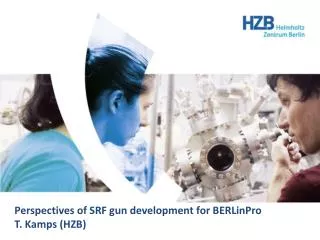
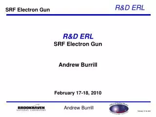
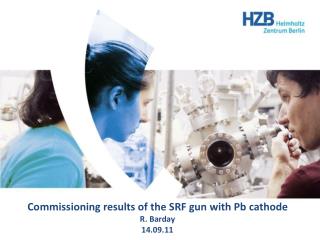
Commissioning results of the SRF gun with Pb cathodeR. Barday14.09.11
Energy Recovery Linac BERLinPro 32 m Beam dump Main linac Merger SRF Gun Booster 6 m demonstration of the feasibility to use ERL technology for future synchrotron light sources Undulator 25 m final beam parameters are determined by the performance of the electron source: SRF gun
Electron source Development of the SRF gun in a staged approach • Stage A • SC cathode on the back wall • ofthe SC cavity • Pb: robust, fast response time • Work function ~(4-5) eV→ UV laser • emissionfrom a fewatomiclayers • highreflectivity • QE ~ few 10-4: toolowtoproducehighaveragecurrent • High peakcurrent, comparabletotheBERLinProrequirements • Stage B • Implementationof NC cathodewithhigh QE at VIS in the SRF gun • Stage C • High power operation
Gun cavity with diagnostics beam line plasma arc deposition few hunderd nm thick Pb cathode film R. Nietubyc first electron beam 21st of April 2011 g e
Vacuum system ok for Pb cathode, cavity, bad for CsK2Sb cathode Particle free assembly Beam line is not yet baked out. TSP is not yet activated Planed for October 2011… P<1E-8 mbar
QE distribution g photocathode e QEmetal<10-4 Plaser~1.5 mW → Ie≤50 nA • Schottky effect (field dependent electron emission) • describes the lowering of the electron affinity (work function) • leads to an encreased electron emission (QE) phase=25 degr.
QE distribution g photocathode e QEmetal<10-4 Plaser~1.5 mW → Ie≤50 nA QEmax ~ 3.6*10-5 • Schottky effect (field dependent electron emission) • describes the lowering of the electron affinity (work function) • leads to an encreased electron emission (QE)
In situ laser cleaning Laser cleaning removes the contaminations from the surface. Laser cleaning improve QE in terms of absolute value and uniformity. BUT! High laser density can damage the photocathode/substrate. 7 laser cleaning runs with laser density between 0.045 mJ/mm2 and 0.23 mJ/mm2 were performed at HZB. KrF excimer laser (Xantos XS) l=248 nm (~5 eV) 5 ns pulse duration (FWHM) Repetition rate 500 Hz Cathode surface was irradiated for 10 minutes
In situ laser cleaning • firstlasercleaning • energy density~0.04 mJ/mm2 • secondlasercleaning • energy density~0.09 mJ/mm2 • thirdlasercleaning • energy density~0.09 mJ/mm2 Pbcathode start laser cleaning
In situ laser cleaning • before laser cleaning • QEmax~3.6E-5 • first laser cleaning • energy density~0.04 mJ/mm2 • QEmax~4.8E-5 • second/third laser cleaning • energy density~0.09 mJ/mm2 • QEmax~4.7E-5 ~factor 2.5 QEmax~30%
In situ laser cleaning During 4th laser cleaning the left side of the cathode was cleaned with the energy density of 0.23 mJ/mm2 fluorescence Nb
In situ laser cleaning trapped He was released during the laser cleaning Tsurface>4K?
In situ laser cleaning Metal cathodes installed in the rf guns typically have lower QE than the one of the test probe. QE of the cathode is 10 times higher than for cleaned Nb Imax=50 nA demonstrated QEmax=9.0E-5 06.07.11 QEmax=3.6E-5 16.06.11 HZB data for QEmax J.Smedley, PRST-AB 11, 013502 (2008)
Phase scan Epeak=12 MV/m tlaser(FWHM)=2ps Epeak=18 MV/m; 10 degr. 0.45 pC FWHM~0.9 ps Epeak=18 MV/m Epeak=18 MV/m tFWHM=2.6 ps
Phase scan To the first order approximation, QEmetal near photoemission threshold can be expressed as
Dark current bE0 Time averaged field emission current E0 oxides/carbides • field enhancement factor: • ideal surface field E is increased to a local microscopic field Em: b=Em/E Epeak=17 MV/m emission around 900 launch phase Epeak=15 MV/m
Dark current bE0 Time averaged field emission current E0 oxides/carbides • field enhancement factor: • ideal surface field E is increased to a local microscopic field Em: b=Em/E Fowler-Nordheim plots for 1.6 cell SRF gun with Pb cathode b=540 b=230 b=180 β was calculated for =4.0 eV
This work is a collaborative effort by: W. Anders, R. Barday, A. Jankowiak, T. Kamps, J. Knobloch, O. Kugeler, A. Matveenko, A. Neumann, T. Quast, J. Völker, Helmholtz-Zentrum Berlin für Materialien und Energie GmbH, Berlin, Germany J. Sekutowicz, DESY, Hamburg, Germany J. Smedley, BNL, Upton, Long Island, New York, USA P. Kneisel, JLAB, Newport News, Virginia, USA R. Nietubyc, The Andrzej Soltan Institute for Nuclear Studies, Swierk/Otwock, Poland J. Teichert, HZDR, Dresden, Germany