Download
1 / 15
150 likes | 324 Views
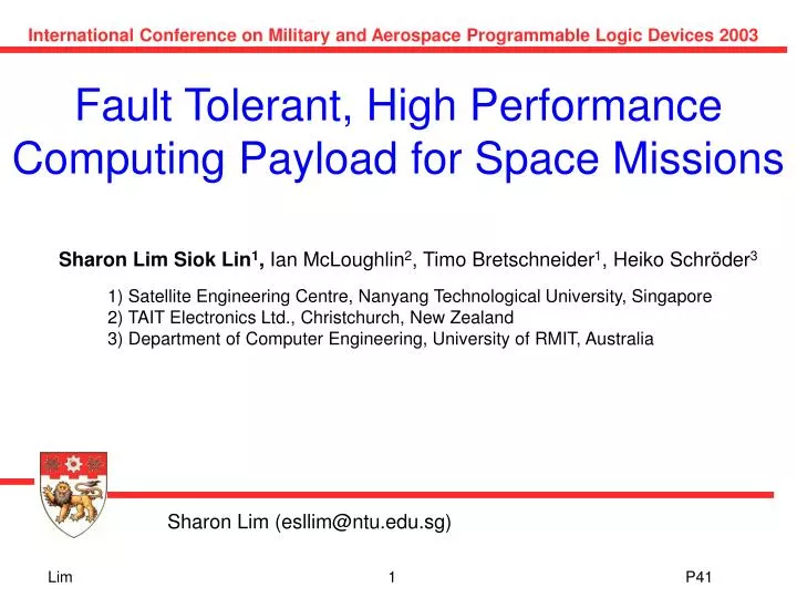
International Conference on Military and Aerospace Programmable Logic Devices 2003. Fault Tolerant, High Performance Computing Payload for Space Missions. Sharon Lim Siok Lin 1 , Ian McLoughlin 2 , Timo Bretschneider 1 , Heiko Schröder 3

E N D
International Conference on Military and Aerospace Programmable Logic Devices 2003 Fault Tolerant, High Performance Computing Payload for Space Missions Sharon Lim Siok Lin1, Ian McLoughlin2, Timo Bretschneider1, Heiko Schröder3 1) Satellite Engineering Centre, Nanyang Technological University, Singapore 2) TAIT Electronics Ltd., Christchurch, New Zealand 3) Department of Computer Engineering, University of RMIT, Australia Sharon Lim (esllim@ntu.edu.sg) Lim 1 P41
Fault Tolerant, High Performance Parallel Processing Unit (PPU) onboard XSat XSat is a low-earth-orbit micro-satellite developed by Nanyang Technological University of Singapore. Remote-sensing mission Launch date: 2006 Primary Mission Payload: IRIS Multispectral Camera (10m resolution) Secondary Mission Payloads: Parallel Processing Unit (PPU) Advanced Data Acquisition Module (ADAM) Lim 2 P41
ADCS Actuators ADCS Sensors Attitude Deter.Control System CAN 0 CAN 1 TT&C Further Bus Components On-Board Computer GPS Power CAN 2 CAN 3 X-Band (Transmission) IRIS Camera RAMDISK Parallel Processing Unit ADAM Instrument LVDS Link XSat Bus Architecture Lim 3 P41
685 km Singapore Why onboard high performance Parallel Processing Unit (PPU) is required? Satellite Speed: 7 km/s Image Acquisition Speed: 81Mbit/s Image Data generated per orbit: 300 Gbit/orbit Data downlink rate: 50Mbps Maximum Downlink Capability: 30 Gbit/orbit On-board image analysis and Compression Increase downlink capacity Or increase value of downlink? Lim 4 P41
Onboard Image Processing (Classification, Segmentation, compression) Compression E=1/16 E=1/16 Not likely Q*CR Q*CR CR ratio ( =4 loss - less) E=5/16 E=5/16 E=5 E=5 Q*CR*CG Q*CR*CG Q*CR*CG*SG Q*CR*CG*SG LOSSY LOSSY =60 =60 E=5/2 E=5/2 E=1/64 E=1/64 Q Q E=5/64 E=5/64 E=5/4 E=5/4 Q*CG Q*CG Q*CG*SG Q*CG*SG Classification gain Classification gain CG= CG= ( ( 5, 1 in 5 images 5, 1 in 5 images contain useful information) contain useful information) Segmentation gain Segmentation gain (SG=16, 1/16 of a useful image is useful) (SG=16, 1/16 of a useful image is useful) Efficiency of satellite downlink data increased Lim 5 P41
Design Solution Dynamic reconfigurable fault tolerant processor array based on COTS processors + Processor Interconnection via reconfigurable routing platforms such as FPGAs + Configurable network topology (mesh, linear, torus) Lim 6 P41
Parallel System Architecture SN2 SN3 Microcontroller with CAN Microcontroller with CAN PN1,4 PN1,3 PN2,3 PN2,4 SN1 SN4 CAN 2 CAN 3 PN1,2 FPGA1 Active- Master FPGA2 Passive- Master PN2,2 PROM PROM PN1,1 PN2,1 RAMDISK Interface 1 RAMDISK Interface 2 PN3,1 FPGA3 Slave FPGA4 Slave PN4,1 Flash Flash Flash Flash PN3,2 PN4,2 Flash Flash Flash Flash Flash Flash Flash Flash SN8 SN5 PN3,4 PN3,3 PN4,3 PN4,4 SN7 SN6 Flat 4-FPGA and 24-processor system based on Xilinx Virtex FPGAs and SA1110 StrongArm processors. Lim 7 P41
Payload Operation Modes Mode 2 Mode 3 Lim 8 P41
Network Topology Table (configuration for Mesh) Logical Processor Identifier Logical Processor Identifier of North, South, East and West Neighbours North South East West 1 5 2 2 6 3 1 : : : : : : : : : : 16 12 15 Why Mesh Processing Array ? Mesh Logical Processing Array 1 2 3 4 5 6 7 8 9 10 11 12 13 14 15 16 • Mesh suits the communication pattern for many image processing applications • Incurs reasonable network routing cost • Can be generalised to a linear array or wrapped-around to a torus array Lim 9 P41
Fault Tolerant Mesh • Each logical working cell in the mesh is assigned to a physical processor in the parallel cluster. • Logical-to-physical processor mapping for the mesh is dynamically configurable in orbit due to processor faults. • A fault tolerant 4X4 logical mesh processing array can be established as long as at least 16 processors out of 24 physical processors are working. • Processor Remapping Algorithm ensures that the logical-to-physical processor mapping minimises inter-FPGA processor communication. • Physical Routing Tables are configurable to support the fault tolerant mesh network for all atomic fault patterns. Lim 10 P41
FPGA Local and Global Routing Structure FPGA local and global routing tables are dynamically configurable to reflect changes in the logical-to-physical processor mapping. • FPGA Local Router • Fully connected network for intra-FPGA processor communication. • FPGA Global Router • Handles communication with external resources (e.g. CAN, RAMDISK) • Handles the communication transfer of the mesh network channels, a token-based global broadcast channel and a CAN command channel among FPGAs. • The various network channels are multiplexed onto the inter-FPGA 160Mbps serial links. Lim 11 P41
Processor Remapping Boundary Conditions Theorem: Given a 2x2 array of FPGAs, each connected to N(N+1) processors, a maximum of (N+1) connections between adjacent FPGAs and one connection between diagonal FPGAs are required for the processors to be connected to a 2Nx2N mesh, assuming the sum of working processors is at least 4N2. • Boundary Conditions • Links between adjacent FPGAs <= N + 1 • Links between diagonal FPGAs <= 1 Processor Remapping Heuristics A processor remapping algorithm that satisfies the boundary conditions for all values of N is developed Lim 12 P41
Physical Processor Array Logical 4X4 Mesh Processor Array FPGA 0 FPGA 1 PN18 PN0 PN1 PN19 Working PNs PN7 PN6 L0 L0 PN4 PN10 PN8 PN7 PN20 PN2 PN3 PN21 L1 PN8 PN9 L2 L3 L1 L2 PN4 PN22 PN23 PN5 PN10 PN11 PN0 PN2 PN6 L4 PN22 L10 L9 L10 L9 L5 L3 L4 L5 PN13 PN15 PN21 PN18 L6 Serial Links PN12 PN13 PN14 PN16 PN17 PN19 L6 L7 L7 L8 PN14 PN15 L8 PN16 PN17 FPGA 2 FPGA 3 Faulty PNs Processor Remapping for a 4X4 Mesh Spare PNs Boundary Conditions for N=2 No of links between adjacent FPGAs <= 3 No of links between diagonal FPGAs <= 1 Diagram illustrates that boundary conditions are satisfied in the physical-to-logical processor mapping. Lim 13 P41
Remapping Scenarios for a 6x 6 and 8 x 8 mesh array Scenario 2 A(-5) B(+1) C(+3) D(+3) Scenario 1 A(-7) B(+3) C(+1) D(+3) Identify minimum working processor set for a 6x6 array Scenario 2 A(-12) B(+4) C(+4) D(+4) Identify minimum working processor set for a 8x8 array Scenario 1 A(-4) B(-2) C(+3) D(+3) Lim 14 P41
Processor Remapping Heuristics? Design a Remapping Algorithm that achieves optimal processor mappingfor a 2Nx2N mesh Scaled to kXk FPGA array Change current redundant processor ratio Simplify remapping heuristics from 1/(N+1) to ? Using feedback on current fault pattern to simplify heuristics Lim 15 P41