Frequency modulation and circuits
Frequency modulation and circuits. Lecture 4. Review of Modulation Circuits. AM Generation DSBSC Generation FM Generation. AM Generation.

Frequency modulation and circuits
E N D
Presentation Transcript
Frequency modulation and circuits Lecture 4
Review of Modulation Circuits • AM Generation • DSBSC Generation • FM Generation
AM Generation • The function of an AM modulator is to modulate a carrier wave using an intelligence signal, which results in sum and difference frequencies, together with the carrier.
A possible way to achieve this is to use an operational amplifier to electrically sum the two signals as shown in the figure below. In such an arrangement the two signals will remain independent of each other.
The production of a typical AM wave requires the use of a non-linear device, such as a transistor or diode. A non-linear device is one that produces an output, which is not proportional to the input. An example of a circuit, which produces an AM wave, is shown.
The result of using the diode and resistor is to clip the negative half of the composite signal. The result is the output signal shown. It will be noticed that this signal is only the top half of the AM wave form.
To produce the full AM wave will require the use of a tank circuit. A diagram of the tank circuit is shown together with its output
If this circuit is incorporated into the original non-linear modulator circuit, the full AM wave can be produced
A diode ha s no gain. To produce gain, a transistor could be used in place of a diode. The circuit is as shown below.
DSBSC Generation Circuits used to obtain DSBSC are called balanced modulators. The figure below shows an example of a balanced modulator. It uses diodes as the non-linear devices.
Circuits used to obtain DSBSC are called balanced modulators. The figure below shows an example of a balanced modulator. It uses diodes as the non-linear devices. The diodes are paired and are turned on and off during the positive and negative half of the carrier frequency cycle.
During the positive half, D1 and D4 are on and the other two are off. The circuit will therefore look as follows
During the negative half, D2 and D3 are on and the other two are off. The resulting circuit is shown. The modulating signal undergoes a 180o phase shift.
The current produced by the carrier signal is split at the centre taps of the transformers and flow in opposite directions. This leads to their cancellation as they produce magnetic fields, which are equal in magnitude but opposite in phase.
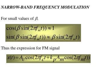
Frequency Modulation • In this the instantaneous frequency of the carrier is caused to vary by an amount proportional to the amplitude of the modulating signal. The amplitude is kept constant. • More complex than AM this is because it involves minute changes in frequency • FM is more immune to effects of noise • FM and PM are similar
Assume we have a carrier at a frequency of 100MHz, called the resting frequency. If a modulating signal is then applied, this will cause the carrier to shift (deviate) from its resting frequency by a certain amount. If the amplitude is increased then the amount of deviation also increases. The rate is proportional to frequency of the intelligence signal. If the signal is removed then the carrier frequency shifts back to its resting frequency. This shift in frequency compared with the amplitude of the modulating voltage is called the deviation ratio.
The deviation ratio is also called the deviation constant and it defines how much the carrier frequency will change for a given input voltage level. The units are kHz/V Example Given that the deviation constant is 1kHz/10mV, what is the shift in frequency for a voltage level of 50 mV? Frequency deviation =
Mathematical representation of FM The following equation can be used to represent FM where fc is the unmodulated carrier frequency k is a proportionality constant and the last term is the modulating voltage It will be seen that the maximum deviation will occur when the cosine term is unity and hence we obtain maximum deviation
It can be shown that the instantaneous value of the FM voltage is given by The modulation index for FM is defined as To solve for the frequency components of the FM requires the use of Bessel functions.
This solution may be shown to be given by To evaluate the individual values of J is quite tedious and so tables are used.
Observations • Unlike AM where there are only three frequencies, FM has an infinite number of sidebands • The J coefficients decrease with n but not in any simple form and represent the amplitude of a particular sideband. The modulation index determines how many sideband components have significant amplitudes • The sidebands at equal distances from fc have equal amplitudes • In AM increase depth of modulation increases sideband power and hence total transmitted power. In FM total transmitted power remains constant, increase depth of modulation increases bandwidth • The theoretical bandwidth required for FM transmission is infinite.
Examples In an FM system when the audio frequency is 300 Hz and the audio voltage is 2.0V, the deviation is 5kHz. If the audio voltage is now increased to 6V what is the new deviation? If the voltage is now increased to 9V and the frequency dropped to 100Hz what is the deviation? Find the modulation index in each case.
Find the carrier and modulating frequencies, the modulating index, and the max. deviation of an FM wave below. What power will the wave dissipate in a 10 ohm resistor? Compare this with: Modulating index=5 as given. Power,
What bandwidth is required to transmit an FM signal with intelligence at 12KHz and max deviation 24 kHz Consult Bessel function table to note that for modulating index of 2, components which exist are J1,J2,J3,J4 apart from J0. This means that apart from the carrier you get J1 at +/-10kHz, J2 at +/- 20kHz, J3 at +/- 30kHz and J4 at +/- 40 kHz. Total bandwidth is therefore 2x40=80kHz.
Carson’s Rule This is an approximate method used to predict the required bandwidth necessary for FM transmission About 98% of the total power is included in the approximation.
For an FM signal given by If this signal is input into a 30 ohm antenna, find • the carrier frequency • the transmitted power • the modulating index • the intelligence frequency • the required bandwidth using Carson's rule and tables • the power in the largest and smallest sidebands
AM Vs FM systems In both systems a carrier wave is modulated by an audio signal to produce a carrier and sidebands. The technique can be applied to various communication systems eg telephony and telegraphy Special techniques applied to AM can also be applied to FM Both systems use receivers based on the superheterodyne principle
In AM, the carrier amplitude is varied whereas in FM the carrier frequency is varied • AM produces two sets of sidebands and is said to be a narrowband system. FM produces a large set of sidebands and is a broad band system • FM gives a better signal to noise ratio than AM under similar operating conditions • FM systems are more sophisticated and expensive than AM systems
Transmitters In an AM transmitter, provision must be made for varying the carrier amplitude whilst for FM the carrier frequency is varied. AM and FM modulators are therefore essentially different in design. FM can be produced by direct frequency modulation or by indirectly phase modulation. The FM carrier must be high usually in the VHF band as it requires large bandwidth which is not available in the lower bands.
Receivers The FM and AM receivers are basically the same, however the FM receiver uses a limiter and a discriminator to remove AM variations and to convert frequency changes to amplitude variations respectively. As a result they (FM) have higher gain than AM. FM receivers give high fidelity reproduction due to their large audio bandwidth up to 15 kHz compared with about 8 kHz for AM receivers.