Download
1 / 26
310 likes | 644 Views
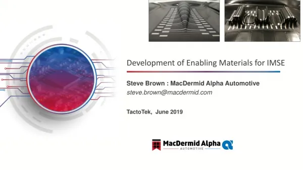
Development of Enabling Materials for IMSE. TactoTek , June 2019. Steve Brown : MacDermid Alpha Automotive steve.brown@macdermid.com. Printed Electronics - Ecosystem / Segments. Injection Molded Structural Electronics. Flexible Hybrid Electronics. Stretchable Electronics.

E N D
Development of Enabling Materials for IMSE TactoTek, June 2019 Steve Brown : MacDermidAlpha Automotive steve.brown@macdermid.com
Printed Electronics - Ecosystem / Segments Injection Molded Structural Electronics Flexible Hybrid Electronics Stretchable Electronics Printed Electronics FHE (Flexible PCBs) Multiple Stretching Events One Time Thermoforming No Stretching / Forming PC Substrate TPU Substrate PET Substrate Typically - Polyimide
IMSE is Integration of: IMSE - Introduction
Automotive Trends: Massive increase of ElectronicsHMI & Smart Surfaces Emerging Automotive Trends: Ever increasing use of Electronics in Automotive: • Especially, through HMI in Dashboard “Cockpit”, and • Broadly in overall automotive (sensors, etc.) • Weight Reduction. Key Enabling Technology: IMSE • Integration of Electronics, Decorative, and Structural Parts (In-mold Decoration & Functional Electronics). • Provides design Flexibility. • Enables next Generation ICE (Information, Communications and Entertainment) through capacitive touch, displays, sensors, etc.
Thermoformed Structures: Multiple Factors could potential affect Performance 2D Printed Circuits Injection Moulded Device 3D Formed Circuits Thermoforming (Vacuum or High-Pressure,150-170C) Injection Moulding (275 -325C) Screen Printing Understanding and Development of Test and Application Process for IMSE is Key to Success
Electrical Conductivity Objectives • Generate reproducible, quantitative, electrical conductivity measurements. • Simplify and Automate the technique. Test Procedure • 32 Line comprise of 8 set of 4 lines with a width of 100 um, 200 um, 500 um and 1000 um. • All lines printed using screen mesh of thickness less than 20 um. • Resistance values of each line measured before and after the molding. • Change in resistance plotted against the strain percentage. • Fully automated ‘resistance measurements’.
Ink Formability Testing Objectives • Use various forming shapes to provide range of stretching, bending and curvature attributes. • Generate systematic quantitative forming measurements. Male Variable Fillet Female Tilted Cone Male Variable Angle Female Variable Stretch Female Variable Fillet Female Variable Angle Male Tilted Cone
Formable Circuitry: Silver & Dielectric Inks Highly formable conductive silver and dielectric inks, designed for thermoforming, in applications employing Polycarbonate (PC) film and PET substrates. • Silver Ink - Requirements • Excellent electrical conductivity after thermoforming. • Excellent adhesion and compatibility with PC substrates, dielectric inks, various emulsion coatings and decorative (graphic) inks. • Capable of forming deep draw configurations. • Dielectric Ink - Requirements • Provide uniform, pin-hole free, thin insulating or encapsulation films. • Enable variety of crossover structures for low voltage circuits. • Excellent adhesion and compatibility with PC & PET substrates, various emulsion coatings and decorative (graphic) inks. • Excellent electrical insulation after thermoforming.
Formable Silver Inks - Performance Measurements Resistance Data of formable Silver Inks on PC substrates (1000 & 500 micron lines). • 500µm at 42% • Before: 29 Ω • After: 113 Ω • Changes: ~ 4 times • 1000µm at 46% • Before: 15 Ω • After: 47 Ω • Changes: ~ 3 times
Ultra Low Temperature Solders (ULTS) Alternatives to ECA’s
Why there are no Flex PET-based PCBs? PET-Based PI-Based SAC Solders ECAs PET-Based FPCBs Low Temp. Solders Screen Printing Stencil Printing PETs for Polymer Thick Films Polyimide for FPCBS Example: FPCBs used in Smartphones, Laptops, etc. Example: MTS, Sensors, etc.
PET Flex PCBs vs. PolyimideFlex PCBs Polyimide Substrates are Expensive Lower cost of PET Substrates Yellow / Orange Water Clear / Translucent Potentially lower warpage (due to lower processing temp.) Higher Warpage Higher Arc Resistance Superior Electrical Performance Self Alignment of Solders vs. use ECAs which do not self-align Simplified Assembly >> Lower Cost of Ownership !!!
Alignment of Components • The importance of this cannot be underestimated • IMSE typically use Electrically Conductive Adhesives (ECA’s) to attach components such as LED’s • Solder allows “self alignment” of components …..or float. • ECA’s don’t….so you end up with poor aesthetics from misaligned parts.
Product Development Steps 1. ULTS Alloy 2. Chemistry 3. Applications Ultra Low Temperature, Alloy Development Paste Chemistry Development Process Development
Innovative High Rel Alloy Offering Standard Benchmark Maxrel Plus High Creep Resistant (Operating Temperature ~150°C) Alloy SAC305 SACX Alloy Melting Point Low Ag SACX Alloy Drop Shock Resistant Alloy) Indus Intermediate Temperature Assembly Alloy (205°C) HRL1 Differentiated Offering for FPCBs HRL1 Low Temperature Assembly Alloy (Off-Eutectic) SBX02 Low Temperature Assembly Alloy (Eutectic: 138°C) ULTS Substrate Film Tg Paper PC PEN PET Polyimide
ULTS : PET Test Vehicle Passives (1608 & 0603) DPAK Bottom Terminated Components (BTCs) (MLF68) BGA256 CSP Components (Fine Feature) RSB Evaluation
Print >> Reflow Images - Passives (1608) Microscopic images of 1608 after 145C Soak N2 Microscopic images of 1608 after 145C HAT N2
ULTS Solder Paste – Soldering Summary • Both Solder Pastes shows complete coalescence and smooth surface on Heat Stabilized PET Substrates. 145C HAT N2 145C Soak N2
Reliability testing – IPC Surface Insulation Resistance Representative optical microscopic images of the coupons processed with PNC1803D
Thermal Cycling - Profiles Evaluated Soak Profile HAT Profile Temperature / ֯C Peak 145 ֯C air: 120 sec Peak 140 ֯C N2: 120 sec Peak 135 ֯C N2: 120 sec Temperature / ֯C Peak 145 ֯C air: 10 sec Peak 140 ֯C N2: 14 sec Peak 135 ֯C N2: 13 sec Time / sec Time / sec
Coalescence of Joints: Microscopic Image of 1608 Joints Not melted
Mechanical Reliability Investigation of mechanical reliability of SnBiIn paste Joints • PCB with 1608 components were evaluated. • Atmosphere: Gas phase • Max. Temp.: 85 ℃ • Min. Temp.: 0 ℃ • Total cycle number: 1500 cycles 1 cycle: 1 hrs 85 ℃ 30 min 30 min 0 ℃ Gain shear stress until breaking joints Die Shear Bonder Test speed: 200 um/s
Results: Joint Strength of Components • Soak Profile tend to offer lower shear force of all of joints than HAT profile, however they are totally reliable for shear test in the all of alloys. • 140C and 145C Soak and HAT profiles showed reliable performance after 1500Cycles. • Recommend Profiles: 145CSoak or HAT Profile.