Lecture 17: Continuous-Time Transfer Functions
180 likes | 822 Views
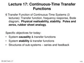
Lecture 17: Continuous-Time Transfer Functions. 6 Transfer Function of Continuous-Time Systems (3 lectures): Transfer function, frequency response, Bode diagram . Physical realisability, stability. Poles and zeros, rubber sheet analogy. Specific objectives for today:

Lecture 17: Continuous-Time Transfer Functions
E N D
Presentation Transcript
Lecture 17: Continuous-Time Transfer Functions • 6 Transfer Function of Continuous-Time Systems (3 lectures): Transfer function, frequency response, Bode diagram. Physical realisability, stability. Poles and zeros, rubber sheet analogy. • Specific objectives for today: • System causality & transfer functions • System stability & transfer functions • Structures of sub-systems – series and feedback
Lecture 17: Resources • Core material • SaS, O&W, 9.2, 9.7, 9.8 • Background material • MIT Lectures 9, 12 and 19
Review: Transfer Functions, Frequency Response & Poles and Zeros • The system’s transfer function is the Laplace (Fourier) transform of the system’s impulse response H(s) (H(jw)). • The transfer function’s poles and zeros are H(s)Pi(s-zi)/Pj(s-pi). • This enables us to both calculate (from the differential equations) and analyse a system’s response • Frequency response magnitude/phase decomposition • H(jw) = |H(jw)|ejH(jw) • Bode diagrams are a log/log plot of this information H(jw)
System Causality & Transfer Functions • Remember, a system is causal if y(t) only depends on x(t), dx(t)/dt,…,x(t-T) where T>0 • This is equivalent to saying that an LTI system’s impulse is h(t) = 0 whenever t<0. • Theorem The ROC associated with the (Laplace) transfer function of a causal system is a right-half plane • Note the converse is not necessarily true (but is true for a rational transfer function) • Proof By definition, for a causal system, s0ROC: • If this converges for s0, then consider any s1>s0 • so s1ROC s-plane Im x Re s=jw
Examples: System Causality • Consider the (LTI 1st order) system with an impulse response • This has a transfer function (Laplace transform) and ROC • The transfer function is rational and the ROC is a right half plane. The corresponding system is causal. • Consider the system with an impulse response • The system transfer function and ROC • The ROC is not the right half plane, so the system is not causal
System Stability • Remember, a system is stable if , which is equivalent to bounded input signal => bounded output • This is equivalent to saying that an LTI system’s impulse is |h(t)|dt<. • Theorem An LTI system is stable if and only if the ROC of H(s) includes the entire jw axis, i.e. Re{s} = 0. • Proof The transfer function ROC includes the “axis”, s=jw along which the Fourier transform has finite energy • Example The following transfer function is stable s-plane Im x Re s=jw
Causal System Stability • Theorem A causal system with rational system function H(s) is stable if and only if all of the poles of H(s) lie in the left-half plane of s, i.e. they have negative real parts • Proof Just combine the two previous theorems • Example • Note that the poles of H(s) correspond to the powers of the exponential response in the time domain. If the real part is negative, they exponential responses decay => stability. Also, the Fourier transform will exist and the imaginary axis lies in the ROC s-plane Im x x -2 -1 Re s=jw
H(jw) -wc wc w LTI Differential Equation Systems • Physical and electrical systems are causal • Most physical and electrical systems dissipate energy, they are stable. The natural state is “at rest” unless some input/excitation signal is applied to the system • When performing analogue (continuous time) system design, the aim is to produce a time-domain “differential equation” which can then be translated to a known system (electrical circuit …) • This is often done in the frequency domain, which may/may not produce a causal, stable, time-domain differential equation. • Example: low pass filter
x y System 1 System 2 x y System 1 Structures of Sub-Systems • How to combine transfer functions H1(s) and H2(s) to get input output transfer function Y(s) = H(s)X(s)? • Series/cascade • Design H2() to cancel out the effects of H1() • Feedback • Design H2() to regulate y(t) to x(t), so H()=1 + - System 2
Series Cascade & Feedback Proofs • Proof of Series Cascade transfer function • Proof of Feedback transfer function x w y H1(s) H2(s) y x + H1(s) - w H2(s)
Example: Cascaded 1st Order Systems • Consider two cascaded LTI first order systems • The result of cascading two first order systems is a second order system. However, the roots of this quadratic are purely real (assuming a and b are real), so the output is not oscillatory, as would be the case with complex roots. x w y H1(s) H2(s)
u(t) y(t) x(t) e(t) + C(s) P(s) - Example: Feedback Control • The idea of feedback is central for control (next semester) • The aim is to design the controller C(s), such that the closed loop response, Y(s), has particular characteristics • The plant P(s) is the physical/electrical system (transfer function of differential equation) that must be controlled by the signal u(t) • The aim is to regulate the plant’s response y(t) so that it follows the demand signal x(t) • The error e(t)=x(t)-y(t) gives an idea of the tracking performance • Real-world example • Control an aircraft’s ailerons so that it follows a particular trajectory
Example Continued … High Gain Feedback • Simple control scheme (high gain feedback), • C(s)=k>>0 • u(t) = ke(t) • For this controller, the system’s response • as desired, when k is extremely large • The controller can be an operational amplifier • While this is a simple controller, it can have some disadvantages.
Lecture 17: Summary • System properties such as stability, causality, … can be interpreted in terms of the time domain (lecture 3), impulse response (lecture 6) or transfer function (this lecture). • For system causality the ROC must be a right-half plane • For system stability, the ROC must include the jw axis • For causal stability, the ROC must include Re{s}>-e • We can use the block transfer notation to calculate the transfer functions of serial, parallel and feedback systems. • Often the aim is to design a sub-system so that the overall transfer function has particular properties
Exercises • Theory • Prove the closed loop transfer function on Slide 12 • SaS, O&W, 9.15, 9.16, 9.17, 9.18 • Matlab • Verify the cascaded response on Slide 11 in Simulink, by cascading two first order models and comparing the response with the equivalent 2nd order model (i.e. pick values for a and b (which are not equal)), • NB the Continuous-System Simulink notation is of the form 1/s, s, 1/(s+a), I.e. the system blocks can be expressed as transfer functions and they can be chained together which just multiplies the individual transfer functions.