Download
1 / 33
330 likes | 451 Views
Venus Atmosphere Platform Options Reconsidered. Presentation for IPPW-9, Toulouse, June 19, 2012 Graham E. Dorrington School of Aerospace, Mechanical and Manufacturing Technology Royal Melbourne Institute of Technology (RMIT) Australia.

E N D
Venus Atmosphere Platform Options Reconsidered Presentation for IPPW-9, Toulouse, June 19, 2012 Graham E. Dorrington School of Aerospace, Mechanical and Manufacturing Technology Royal Melbourne Institute of Technology (RMIT) Australia
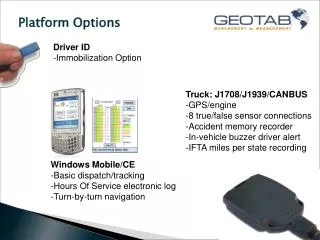
Content VEGA Super-Pressure Balloons (SPBs) VEGA derived vertical wind velocity EVE SPB (some concerns) Alternative platform options Phase Change (Oscillating) Balloons Other concepts
VEGA 1 and 2, June 1985 3.5 m Envelope 13 m Gondola Anemometer Helium-filled spherical Super-Pressure Balloon (SPB) 53.5 km altitude westward drift 46 hr limited by battery capacity Blamont: “Demonstration or feasibility study” (1985)
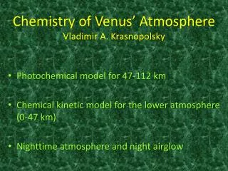
Cytherean Triple Cloud Layer EVE & Vega SPBs Krasnopolsky (2006)
VEGA 1 Pressure (mBar) Temperature (K) Derived vertical wind velocity (m/s) Illumination (lux) Sagdeev et al. Science (1985)
VEGA 1 Pressure (mBar) Temperature (K) Derived vertical wind velocity (m/s) Illumination (lux) Sagdeev et al. Science (1985)
VEGA 2 Pressure (mBar) Temperature (K) Derived vertical wind velocity (m/s) Illumination (lux) Sagdeev et al. Science (1985)
Drift towards downward wind velocity zones C Convection region 48-55 km
Drift towards downward wind velocity zones SPB above convection region drifts laterally towards convergent zones
Drift towards downward wind velocity zones ‘Subduction’ of SPB into downward convergence zone
Drift towards downward wind velocity zones Bobbing in downward winds – dependent on super-pressure stabilisation
Vega 1 Pressure (mBar) Temperature (K) Derived vertical wind velocity (m/s) Illumination (lux) Mainly downward flow, -0.5 m/s Sagdeev et al. Science (1985)
Vega 1 & 2 wake effects 3.5 m Envelope Wake region for downward relative flows 13 m Gondola Anemometer
Wake measurements behind 0.5 m sphere Test using RMIT Industrial Wind Tunnel Facility
Vega 1 A. Derived vertical wind velocity w B. Balloon vertical velocity C. Relative velocity wrel D. Anemometer velocity (extra noise caused by wake)
Vega anemometer data Anemometer velocity Linkin et al. (1985) decided to only use anemometer data to establish zero relative flow conditions And thereby establish the leakage rate (5%) over 46 hours Relative velocity Balloon velocity Relative velocity (triangle symbol) Anemometer velocity (square symbol) Derived vertical wind velocity
Derived vertical wind velocity Vertical equation of motion: Apparent mass term k not properly known for separated flows Drag coefficient term CD only known approximately, 20% error?
Derived vertical wind velocity, w Reduction by Linkin et al. (1985): Linear envelope volume relation (e = elasticity parameter): Linkin et al. (1985) “compute” helium pressure and hence envelope volume in order to derive w
Derived vertical wind velocity Volume of envelope may actually be derived directly, p = P/P0, =TH /TH0, =m/mH0 But elasticity parameter is dependent on modulus of elasticity of TeflonTM (PTFE) envelope (variable in domain of interest), implies that linear volume relation used is doubtful Linkin et al. assumed helium temperature is same as ambient (after float height attained and before sunrise) Any precipitation (?) on envelope would change mass
VEGA SPB summary Vega derived wind velocity may have an error of about +/- 0.4 m/s, but raw flight data is needed to verify this claim What happened to Vega 1 & 2 after transmission loss? They may have completed multiple circumnavigations Or they may have suffered super-heating at midday and subsequent helium venting and premature irreversible descent
EVE (2010) Proposal Float of 240 hours to “guarantee at least one circumnavigation of Venus” at 55 km Science goals include cloud chemistry and measurements of noble gas isotopic ratios, as well as meteorology. Scientific payload (15-20 kg) More power (40 W) and capacity (8600 Wh) than VEGA, solar power augmentation during daytime 5 m diameter envelope for 60 kg float mass (3.5 m VEGA)
Concerns about EVE (2010) ESA concerned that choice of 55 km does not permit sampling of other altitudes, e.g., dense lower cloud with large mode 3 particles (49 km) and unknown UV absorber (70 km) Anemometer will be in downward flow (repeating VEGA again) Smooth sphere is subject to lateral oscillations (could be mitigated by using a JIMSPHERE) Super-heating a midday remains a concern (loss of mission). Vertical stability of SPB is improved by using higher strength envelope with higher e value, but this is weak effect. Terrestrial long endurance SPB experience (e.g. “VORCORE”) has been limited to relatively calm stratospheric flight with low vertical wind velocities (cm/s) but mission loss is typically more than 5%. Heavy helium/hydrogen storage tank (75 kg) required
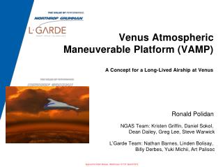
Free Balloon with Phase Change Fluid (PCF) Tandem Configuration Schematic Primary envelope containing helium (or hydrogen) gas Secondary envelope containing PCF Payload and liquid PCF container
Free Balloon with Phase Change Fluid (PCF) Toroidal Configuration Schematic
Phase Change Fluid (PCF) options Higher MW PCFs increase oscillation altitude, but reduce payload fraction
Oscillating Phase Change Balloons Have been demonstrated in Earth troposphere (ALICE) Well known thermodynamics govern predicted oscillation High risk deployment and initial helium/hydrogen inflation can be tested at similar Earth-Venus conditions Secondary envelope offers low altitude safety “buffer” (reducing mission risk) Permits multiple traverses of cloud layers MIL specification electronics possible down to 43 km (PCF evaporation cools payload). Slightly reduced payload ratio
Other Options Requiring Study Infra-Red Montgolfière Fixed-Wing Gliders (6 hours) Parawings (solar power, 10 hours) Vetrolets (wind shear dependent) Etc.
Conclusions VEGA 1 & 2 SPB flights rank with major aeronautical historical events but may not have circumnavigated Venus after power loss For (multiple) circumnavigation of Venus Phase Change Balloons offer: lower risk of premature mission loss multiple traverses of cloud layers