Download
1 / 74
740 likes | 1.01k Views
RAPID PROTOTYPING TECHNOLOGIES Prof. Dr. Bilgin KAFTANOĞLU www.mfge.atilim.edu.tr/kaftanoglu Manufacturing Engineering Department ATILIM UNIVERSITY ANKARA. WHAT IS PROTOTYPING? Essential part of the product development and manufactuing cycle;

E N D
RAPID PROTOTYPING TECHNOLOGIES Prof. Dr. Bilgin KAFTANOĞLU www.mfge.atilim.edu.tr/kaftanoglu Manufacturing Engineering Department ATILIM UNIVERSITY ANKARA
WHAT IS PROTOTYPING? • Essential part of the product development and manufactuing cycle; • Assesing the form, fit and functionality of a design before a significant investment in tooling is made.
Until Recently, prototypes: • were handmade by skilled craftsmen (i.e. High Cost); • adding weeks or months to the product development time (increase time to market) • So: • A few design iterations could be made before tooling went into production; • Seldom optimization of designed parts or at worst parts did not function properly.
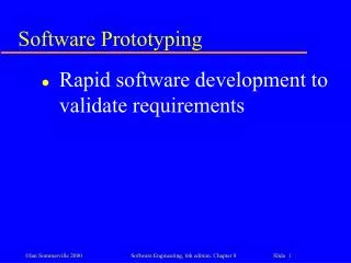
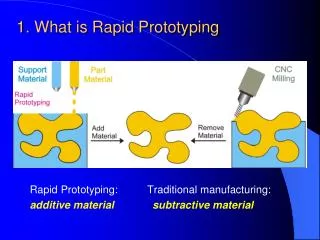
Rapid Prototyping: • name given to a host of related technologies that are used to fabricate physical objects directly from CAD data sources; • These methods are unique in that they add and bond materials in layers to form objects. • Other names: Solid Freeform Fabrication,Layer Manufacturing
With Rapid Prototyping, • Objects can be formed with any geometric complexity without the need for elaborate (very complex) machine setup and jigs and fixtures. • Objects can be made from multiple materials (Such as Aluminum and Polyamide, Copper and Steel), or as composites, or materials can even be varied in a controlled fashion at any location in an object; • The construction of complex objects are reduced to a manageable, straightforward, and relatively fast process.
With Rapid Prototyping, • time to market in manufacturing is reduced; • the product designs are better understood and communicated; • rapid tooling to manufacture those products are made.
The names of specific Rapid Prototyping processes: • Stereolithography (SLA), • Selective laser sintering (SLS), • Fused deposition modeling (FDM), • Laminated object manufacturing (LOM), • Laser Engineering Net Shaping (LENS) • Inkjet Systems and Three Dimensional Printing (3DP). • Each has its singular strengths and weaknesses.
STEREOLITHOGRAPHY • The most widely used rapid prototyping technology. • Builds plastic parts or objects a layer at a time by tracing a laser beam on the surface of a vat of liquid photopolymer (Self Adhesive Material). • Liquid photoplymer quickly solidifies wherever the laser beam strikes the surface of the liquid. • Once one layer is completely traced, it's lowered a small distance into the vat and a second layer is traced right on top of the first. • The layers bond to one another and form a complete, three-dimensional object after many such layers are formed.
The platform in the tank of photopolymer at the beginning of a run.
STEREOLITHOGRAPHY The objects have overhangs or undercuts which must be supported during the fabrication process by support structures. These are either manually or automatically designed and fabricated right along with the object. Upon completion of the fabrication process, the object is elevated from the vat and the supports are cut off. The platform at the end of a print run, shown here with several identical objects.
STEREOLITHOGRAPHY • The second most accurate and best surface finish of any rapid prototyping technology. • Wide range of materials with properties mimicking those of several engineering thermoplastics. Biomedical materials are available, and ceramic materials are currently being developed. • The technology is also notable for the large object sizes that are possible.
STEREOLITHOGRAPHY On the negative side, • Material is expensive, smelly and toxic; • Removing supports may adversely effect surface finish; • Parts often require a post-curing operation in a separate oven-like apparatus for complete cure and stability. Post Curing ensures that no liquid or partially cured resin remains. The ultraviolet "oven" used to cure completed objects.
FUSED DEPOSITION MODELLING • Second most widely used rapid prototyping technology, after stereolithography • A plastic filament is unwound from a coil and supplies material to an extrusion nozzle. • The nozzle: • is heated to melt the plastic and has a mechanism which allows the flow of the melted plastic to be turned on and off. • is mounted to a mechanical stage which can be moved in both horizontal and vertical directions.
FUSED DEPOSITION MODELLING • As the nozzle is moved over the table in the required geometry, it deposits a thin bead of extruded plastic to form each layer. • The plastic hardens immediately after being extruded and bonds to the layer below. • The chamber is held at a temperature just below the melting point of the plastic.
FUSED DEPOSITION MODELLING • Materials: ABS and investment casting wax, and more recently polyamide materials; • Researches for embedding Ceramic and Metal powders in polymer filament is going on. • ABS offers good strength; • Support materials: • Same material: Problems during removing; • Break Away Support System: Easily removed; • Water Works: Water-soluble support material. (in ultrasonic vibration tank)
FUSED DEPOSITION MODELLING • Office-friendly and quiet; • Fairly fast for small parts or for those that have tall, thin form-factors; • Very slow for parts with wide cross sections; • The finish of parts have been greatly improved over the years, but aren't quite on a par with stereolithography. • FDM offers great strength.
INKJET • Uses a single jet each for a plastic build material and a wax-like support material, which are held in a melted liquid state in reservoirs • The materials harden by rapidly dropping in temperature as they are deposited • After an entire layer of the object is formed by jetting, a milling head is passed over the layer to make it a uniform thickness
INKJET • Extremely fine resolution and surface finishes, essentially equivalent to CNC machines; • The technique is very slow for large objects; • While the size of the machine and materials are office-friendly, the use of a milling head creates noise which may be objectionable in an office environment. • Materials selection is very limited and the parts are fragile • Especially used in precise casting patterns for jewelry.
INKJET Jevelry Application A production cut in the middle
3D PRINTING • Developed at MIT; • A measured quantity of powder is first dispensed from a similar supply chamber by moving a piston upward incrementally. • The roller then distributes and compresses the powder at the top of the fabrication chamber. • The jetting head subsequently deposits a liquid adhesive in a two dimensional pattern onto the layer of the powder • The powder becomes bonded in the areas where the adhesive is deposited, to form a layer of the object.
3D PRINTING • No external supports are required during fabrication since the powder bed supports overhangs; • Offers the advantages of speedy fabrication and low materials cost; • Probably the fastest of all RP methods; • Recently color output has also become available; • There are limitations on resolution, surface finish, part fragility and available materials.
LAMINATED OBJECT MANUFACTURING • object cross sections are cut from paper or other web material using a laser or a knife; • The paper is unwound from a feed roll onto the stack and first bonded to the previous layer using a heated roller which melts a plastic coating on the bottom side of the paper • The profiles are then traced by an optics system or knife • Areas to be removed in the final object are heavily cross-hatched with the laser to facilitate removal. • Excess paper is cut away to separate the layer from the web. Waste paper is wound on a take-up roll
LAMINATED OBJECT MANUFACTURING • It can be time consuming to remove extra material for some geometries; • The finish, accuracy and stability of paper objects are not as good as for materials used with other RP methods • Material costs are very low, and objects have the look and feel of wood and can be worked and finished in the same manner • Application: Patterns for sand castings. • Limitations on materials, work has been done with plastics, composites, ceramics and metals. However, available on a limited commercial basis.
Laser Engineered Net Shaping • A technology that is gaining in importance and in early stages of commercialization. • Designed for aerospace industry, especially to produce titanium parts. • A high power laser (1400 W) is used to melt metal powder supplied coaxially to the focus of the laser beam through a deposition head. • The head is moved up vertically as each layer is completed. • Metal powders are delivered and distributed around the circumference of the head either by gravity, or by using a pressurized carrier gas.
Laser Engineered Net Shaping • In addition to titanium, a variety of materials can be used such as stainless steel, copper, aluminum etc. • Materials composition can be changed dynamically and continuously, leading to objects with properties that might be mutually exclusive using classical fabrication methods. • Has the ability to fabricate fully-dense metal parts with good metallurgical properties at reasonable speeds; • Objects fabricated are near net shape, but generally will require finish machining.
Laser Engineered Net Shaping Before and after finish machining
Laser Engineered Net Shaping 120x120x120 cm LENS Machine
Selective Laser Sintering • Sintering: • bonding of the metal, ceramic or plastic powders together when heated to temperatures in excess of approxiamately half the absolute melting tempertaure. • In the industry, sintering is mainly used for metal and ceramic parts (Powder Matallurgy). • After pressing (compaction) of the powder inside mold for deforming into high densities, while providing the shape and dimensional control, the compacted parts are then sintered for achieving bonding of the powders metallurgically.
Selective Laser Sintering Compaction Sintering
Sintering in Rapid Prototyping • Sintering process used in Rapid Prototyping differs from the Powder Metallurgy, such as: • Plastic based powders, in additon to metal powders. • Local sintering, not overall sintering. • Very short sintering period. • Laser (heat source) is exposed to sections to be sintered for a very short time. Hard to achive an ideal sintering. • In some applications, for achieving the ideal sintering, the finished parts are heated in a seperate sintering owen.
Selective Laser Sintering • Invented by Carl Deckard during his Phd. studies in Texas University in 1987. • Offers the key advantage of making functional parts in essentially final materials. • The system is mechanically more complex than stereolithography and most other technologies. • A variety of thermoplastic materials such as nylon, glass filled nylon, polyamide and polystyrene are available. The method has also been extended to provide direct fabrication of metal and ceramic objects and tools.
Selective Laser Sintering Process: 1) Laser beam is traced over the surface the tightly compacted powder to selectively melt and bond it to form a layer of the object.
Selective Laser Sintering Process: 2) Platform is lovered down one object layer thickness to accommodate the new layer of powder
Selective Laser Sintering Process: 3) A new layer of powder is coated on the surface of the build chamber.
Selective Laser Sintering Process: 4) The powder is supplied from the powder bins to the recoater. This process is repeated until the entire object is fabricated.
Selective Laser Sintering • The fabrication chamber is maintained at a temperature just below the melting point of the powder • Heat from the laser need only elevate the temperature slightly to cause sintering. This greatly speeds up the process; • No supports are required with this method since overhangs and undercuts are supported by the solid powder bed; • Surface finishes and accuracy are not quite as good as with stereolithography, but material properties can be quite close to those of the intrinsic materials
Selective Laser Sintering Three Types of Laser Sintering Machines: 1) Plastic Laser Sintering Machine 2) Metal Laser Sintering Machine 3) Sand Casting Laser Sintering Machine
Selective Laser Sintering • Plastic Laser Sintering: • For direct manufacture of styling models, functional prototypes, patterns for plaster, investment and vacuum casting, for end products and spare parts. • Volvo Steering Wheel • Engine Block Pattern • Plaster Invest. Pattern
Selective Laser Sintering • Metal Laser Sintering: • For direct production of tooling, including for plastic injection molding, metal die casting, sheet metal forming as well as metal parts, directly from steel based and other metal powders. • A gear for Volvo Corp. • Die Cast Parts (500 Al parts produced) • Motor Housing
Selective Laser Sintering • Sand Laser Sintering: • Laser Sintering System for direct, boxless manufacture of sand cores and moulds for metal casting. • V6-24 Valve Cylinder Head. • Impeller • Steering Block for a car