Download
1 / 26
260 likes | 291 Views
This presentation discusses the development of a cold cathode solution for electron coolers utilizing Field Emission with Carbon Nanotubes (CNTs). The alternative to thermionic and photocathodes aims to enhance electron beam performance by utilizing Field Emission. Topics include the advantages and challenges of using Carbon Nanotubes, the benefits of Vertically Aligned CNTs, and the optimization of CNT Arrays for improved performance. The talk also covers methods for enhancing emission through doping, decoration, and composite structures. The Cold Cathode Test Bench setup and Fowler-Nordheim Plot results are presented along with proposed improvements and future steps towards longitudinal and transverse energy measurements.

E N D
Cold Cathode Development for Electron Coolers Bruno Galante BE-BI-EABI Day 04-12-2018 bruno.galante@cern.ch
ELENA [1][2] bruno.galante@cern.ch
ELENA e-Cooler Electron Gun Collector [3] bruno.galante@cern.ch
Electron Gun It must produce a • Cold (T⊥ < 0.1eV, T// < 1meV) • Intense electron beam (ne ≈ 1.5x1012 cm-3) Thermionic cathodes limit the performance of electron cooling due to high Tof the emitted beam while photocathodes suffer of an usually quite low lifetime. Alternative solution: Field Emission due to have a Cold Cathode. bruno.galante@cern.ch
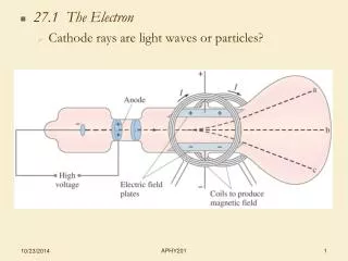
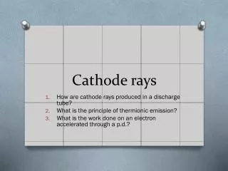
Field Emission • Thermionic Emission: Heating of the cathodethat leads the generation of an electron beamonce the electrons have energy enough to overcome the potential barrier. • Photoemission: Generation of electron by irradiation with a light source with proper energy. • Field Emission: Tunneling of electrons through the barrier applying avery large electric field (~ 107 V/cm) [4][5][6] bruno.galante@cern.ch
Carbon Nanotubes • For flat surfaces the required electric field is too strong. • Possible solution: Field Enhancement with tips • PRO: • High aspect ratio -> High enhancement • Emit at low field, in order of some V/μm • Scalable production techniques • Chemical inertness and stable structure • CONS: • Small emitted current per tip • Screening effects • Impurities and defects [4][5][6][7][8][9] bruno.galante@cern.ch
Vertically Aligned CNTs • Best performances achieved with perfectly aligned CNTs • Screening minimization and dense enough forests S=2h • Length distribution and burn-out Conditioning • Degradation MWNTs better [10][11] bruno.galante@cern.ch
CNT Arrays • Probably best solution -> More studies • Use of catalyst (e.g. Fe, Ni) with different shapes on the substrate • Parameter to optimize: spacing and size of the forests • In Fig. above -> 30µm x 30µm Fe catalyst pattern at pitch distance 125 µm. Best performance achieved: 80 mA/cm2 at about 3 V/µm • In Fig. below -> 1 mA/cm2 at 1,5 V/µm and current densities up to 1,5 A/cm2. FE evaluated using diode configuration at a pressure of 1x10⁻⁸ mbar. Emission area: 4x4mm2. Inter-electrode distance: 0.25mm (spacers). [12][13] bruno.galante@cern.ch
CNT Arrays • Probably best solution -> More studies • Use of catalyst (e.g. Fe, Ni) with different shapes on the substrate • Parameter to optimize: spacing and size of the forests • In Fig. above -> 30µm x 30µm Fe catalyst pattern at pitch distance 125 µm. Best performance achieved: 80 mA/cm2 at about 3 V/µm • In Fig. below -> 1 mA/cm2 at 1,5 V/µm and current densities up to 1,5 A/cm2. FE evaluated using diode configuration at a pressure of 1x10⁻⁸ mbar. Emission area: 4x4mm2. Inter-electrode distance: 0.25mm (spacers). [12][13] bruno.galante@cern.ch
Doping, Decoration and Composite Structures • Doping: Modification of the crystalline structure introducing different elements, e.g. N, O • Decoration: Metal coating using different metals with lower work function • Composite Structures: Add of different structure on the top of the nanotubes to modify work function and/or increase enhancement factor [14]-[20] bruno.galante@cern.ch
Cold Cathode Test Bench Copper Anode Alumina Spacer Copper foil Substrate + CNT Array Vespel Insulator bruno.galante@cern.ch
Cold Cathode Test Bench bruno.galante@cern.ch
Conditioning Test 0.91 V/µm 1.94 V/µm 2.51 V/µm 1.48 V/µm 2.4 V/µm 2.63 V/µm bruno.galante@cern.ch
Fowler-Nordheim Plot bruno.galante@cern.ch
Further Improvements & Next steps • Improvements: • Annealing of samples at 450 degrees in Ammonia atmosphere • Bake-out of the test bench • Better vacuum • Resistor in series with the power supply Ballast Resistor • Next: • Measurement of Longitudinal and Transverse Energy depending on the inter-electrode distance bruno.galante@cern.ch
Thank you “AVA has received funding from the European Union’s Horizon 2020 research and innovation programme under the Marie Skłodowska-Curie grant agreement No 721559.” bruno.galante@cern.ch
References • [1] - https://espace.cern.ch/elena-project/SitePages/Home.aspx[2] - ELENA: the extra low energy anti-proton facility at CERN – S.Maury, W.Oelert, W.Bartmann, P.Belochitskii, H.Breuker, F.Butin, C.Carli, T.Eriksson, S.Pasinelli, G.Tranquille[3] - The ELENA electron cooler: parameter choice and expected performance – G.Tranquille, A.Frassier, L.Joergensen[4] - Electron emission in intense electric fields – R.H.Fowler, Dr.L.Nordheim[5] - Carbon Nanotube Electron Source: from electron beams to energy conversion and optophotonics – AlirezaNojeh[6] - Electron field emission from carbon nanotubes – Y.Cheng, O.Zhou[7] - Vacuum nanoelectronics devices: Novel electron sources and applications – A. Evtukh, H. Hartnagel, O. Yilmazoglu, H. Mimura, D. Pavlidis[8] - Carbon nanotubes for cold electron sources – P.Groning, P.Ruffiex, L.Schlapbach, O.Groning[9] - Carbon Nanotube and related field emitters: Fundamentals and applications – Yahachi Saito [10] - Array geometry, size and spacing effects on field emission characteristics of aligned carbon nanotubes – Y.M.Wong, W.P.Kang, J.L.Davidson, B.K.Choi, [11] - Maximizing the electron field emission performance of carbon nanotube arrays – R.C.Smith, S.R.P.Silva[12] - Patterned selective growth of carbon nanotubes and large field emission from vertically well-aligned carbon nanotube field emitter arrays – J.Sohn, S.Lee, Y.-H.Song, S.-Y.Choi, K.-S.Nam[13] - High emission current density, vertically aligned carbon nanotube mesh, field emitter array – C.Li, Y.Zhang, M.Mann, D.Hasko, W.Lei, B.Wang, D.Chu, D.Pribat, G.Amaratunga, W.I.Milne[14] - The doping of carbon nanotubes with nitrogen and their potential applications – P.Ayala, R.Arenal, M.Rummeli, A.Rubio, T.Pichler[15] - Oxygen and nitrogen doping in single wal carbon nanotubes: An efficient stable field emitter – A.Kumar, S.Parveen, S.Husain, M.Zulfequar, Harsh, M.Husain[16] - Improved field emission properties of carbon nanotubes decorated with Ta layer – Z.Wang, Y.Zuo, Y.Li, X.Han, X.Guo, J.Wang, B.Cao, L.Xi, D.Xue bruno.galante@cern.ch
References • [17] - Highly improved field emission from vertical graphene-carbon nanotube composites – J.-H. Deng, R.-N. Liu, Y.Zang, W.-X. Zhu, A-L.Han, G.-A. Cheng[18] - Highly improved field emission from vertical graphene-carbon nanotube composites – J.-H. Deng, R.-N. Liu, Y.Zang, W.-X. Zhu, A-L.Han, G.-A. Cheng [19] - Enhanced field emission properties of a reduced graphene oxide/carbon nanotube hybrid film – D.D.Nguyen, Y.-T.Lai, N.-H.Tai[20] - Excellent field emission characteristics from few-layer graphene-carbon nanotube hybrids synthesized using radio frequency hydrogen plasma sputtering deposition – J.-H.Deng, R.-t. Zheng, Y.-M.Yang, Y.Zhao, G.-A.Cheng bruno.galante@cern.ch
Fowler-Nordheim Plot bruno.galante@cern.ch
SEM of CNT Array bruno.galante@cern.ch
Longitudinal and Transverse Energy ~ -2kV ~ -2kV r 2) TE 1) LE ~ +1kV ~ -2kV bruno.galante@cern.ch
Grid vs Hole Grid Hole bruno.galante@cern.ch
Grid Effect Grid No Grid bruno.galante@cern.ch